Bladder Volume Tester User’s Manual V1.02
- 8 -
The probe is inserted the “PROBE” socket on the panel.
6.3.2 Ultrasonic probe disconnection
Shutdown the system; hold the red marked part near the probe connector, and pull out the ultrasound
probe connector vertically.
6.4 Install foot switch
Shutdown the system; insert the plug of foot-switch into the “FOOT SW” socket on the back of the
main unit.
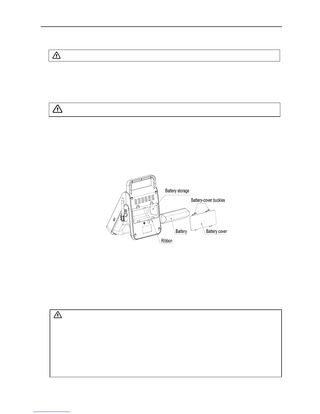
6.5 Install/Remove the battery
1. Install the battery
Pull out the ribbon to make it a natural droop, push the battery in the battery storage and tidy up the
ribbon, finally cover the “Battery cover”.
2. Remove the battery
Hold down the battery-cover buckles above, and remove the battery cover, pull the ribbon and take
out the battery.
Fig. Install, Remove the battery
6.6 Connection to power
1. Connect to the power adapter
Insert the output plug of adapter into DC power input interface, which is on the back of main unit.
2. Connect to the main power supply
Insert the power plug (jack) furnished with the machine into power input socket of the power adapter,
the other end to the mains socket-outlet. The instrument uses three-core power line. It connects with
the protective earth line when power plug inserts into the standard power socket.
Attention:
The waterproof grade of foot switch is IPX1.
Warning:
1. Adapter has no switch. APPLIANCE COUPLER or MAINS PLUG is used as the intended
disconnection device from the supply mains. Do not position the EQUIPMENT the place
where it is difficult to operate the disconnection device.
2. AC/DC adapter is as a part of the equipment, please only use the AC/DC adapter provided
by Kaixin Company.
3. To avoid damaging power adapter or harming people by unexpected fallen, make sure the
power adapter is placed on the leveled desk.
4. The operator must not touch signal input/output and patient simultaneously.
 Loading...