18 Kamstrup A/S • 55122714_A2_GB_04_2021
flowIQ® Gateway
6.4.2 Connecting pulse meters
Some modules are equipped with two pulse inputs, In-A and In-B, to collect and accumulate
pulses. The pulse inputs are physically placed on the module. However, the accumulation and
logging are performed by flowIQ® Gateway. Depending on where the communication module is
placed (slot 1 or slot 2), the pulse inputs will be registered as In-A1 and In-B1 or In-A2 and In-B2.
Thus, you can install two communication modules with two pulse inputs each and connect up
to four pulse meters to flowIQ® Gateway. For examples, see section 10 "Communication module
combinations and examples".
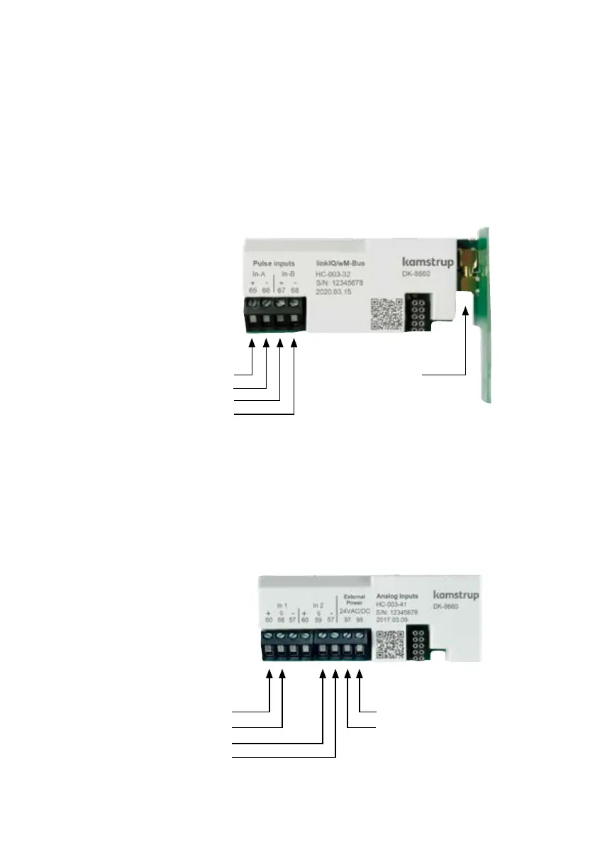
Here is an example of the module HC-003-32: linkIQ®/wM-Bus module:
Upon delivery, the configurations of pulse inputs A and B can be changed with METERTOOL HCW.
The preset value of In-A1 and In-B1 can be set via the front keys, see section 7 "Field deployment –
Configuration".
6.4.3 Connecting Analog input 4…20 mA devices
Module HC-003-41 is equipped with Analog 2 x 4…20 mA inputs. The module writes the values of
the analog signals to the P1 and P2 registers of flowIQ® Gateway. The inputs are physically placed
on the module. However, the accumulation and logging are performed by flowIQ® Gateway. Only
one analog input module is supported in flowIQ® Gateway.
Pulse inputs
Terminal 65: Pulse In-A (+)
Terminal 66: Pulse In-A (-)
Terminal 67: Pulse In-B (+)
Terminal 68: Pulse In-B (-)
Antenna
Terminals
Max cable size 1.5 mm²
External power
Terminal 98: 24 VAC/VDC
Terminal 97: 24 VAC/VDC
Analog inputs
Terminal 60: + supply In 1, In 2
Terminal 58: Signal In 1
Terminal 59: Signal In 2
Terminal 57: - supply In 1, In 2