34 Kamstrup A/S • 55122714_A2_GB_04_2021
flowIQ® Gateway
10 Communication module combinations and examples
Depending on the chosen communication modules installed in module slots 1 and 2, up to 5
meters can be connected and data forwarded from flowIQ® Gateway:
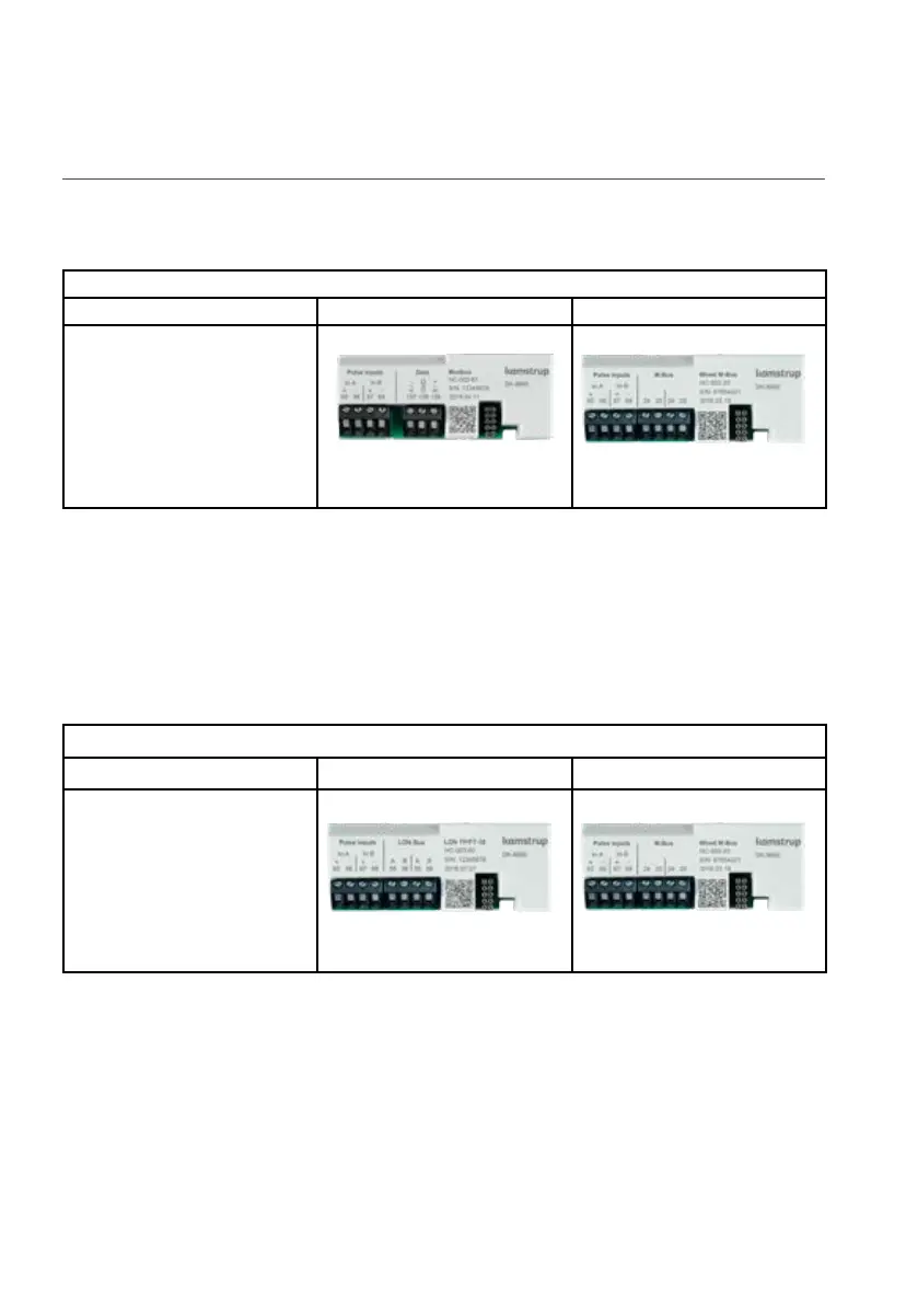
Example 1
Primary connection terminals Module slot 1 Module slot 2
1 x flowIQ® 2200/3200 meter
(serial V1 connection)
3 x Pt500 temperature
sensors
HC-003-67
1 x Modbus RTU, 2 pulse inputs
(In-A, In-B)
HC-003-20/21/22
1 x M-Bus module, 2 pulse inputs
(In-A, In-B)
In example 1, the primary module is connected to 1 x flowIQ® 2200/3200 meter and up to 3 x
Pt500 temperature sensors.
Module slot 1 has a Modbus output with 2 pulse inputs, In-A1 and In-B1.
Module slot 2 has an M-Bus module with 2 pulse inputs, In-A2 and In-B2.
Only V1 data is available on pulse input.
For further information, see the module data sheet.
Example 2
Primary connection terminals Module slot 1 Module slot 2
1 x flowIQ® 2200/3200 meter
(serial V1 connection)
3 x Pt500 temperature
sensors
HC-003-60
1 x LON TP/FT-10, pulse inputs
(In-A, In-B)
HC-003-20/21/22
1 x M-Bus module, 2 pulse inputs
(In-A, In-B)
In example 2, the primary module is connected to 1 x flowIQ® 2200/3200 meter and up to 3 x
Pt500 temperature sensors.
Module slot 1 has a LON output with 2 pulse inputs, In-A1 and In-B1.
Module slot 2 has an M-Bus module with 2 pulse inputs, In-A2 and In-B2.
Only V1 data is available on pulse input.
For further information, see the module data sheet.