5511-185 GB-DE-DK/03.2005/Rev. E1
5
English
WARRANTY
Please read
these instruc-
tions before
installing and
starting to use
an M-Bus system.
Kamstrup’s
guarantee
obligations do
not apply in case
of incorrect
installation.
Initialization is
always necessary
in connection
with start-up
or after service
in the M-Bus
network.
As a complete
test after
installation,
we recommend
you to read all
M-Bus Slaves
and thoroughly
check that all
M-Bus Slaves
have replied,
see paragraph 6.
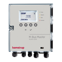
1. Mounting of M-Bus Master
By means of the enclosed angle/wall
bracket you can mount the M-Bus Master
on e.g. a wall. Use the bracket as a tem-
plate to mark the position and drill two
6 mm holes. Screws and rawlplugs are
supplied together with the M-Bus Master.
2. Power supply
The M-Bus Master is to be connected to
230 VAC. The unit has protection class II.
The connection is established by means
of a 2-wire cable through the cable bush.
Furthermore, we refer to national installa-
tion regulations.
3. Electrical connection
Dismount the top part of the M-Bus
Master by unscrewing the two screws at
the sides. Lift off the top part carefully.
Electrical connection as shown in the
drawing:
230 VAC
Terminals 27 and 28
Bus supply
Terminals 60(+) and 61(-)
M-Bus
Terminals 24 and 25, 2 parallel sets,
independent of polarity
RS232
Terminals 62 - Brown - Data
63 - White - REQ
64 - Green - GND
4. Functional control
Having finished mounting and electrical
connection check the power supply on
terminals 60(+) and 61(-), it should be
approx. 60 VDC. Mount the top part
and check that the light emitting diode
marked POWER is constantly lighted.
The light emitting diode marked
OVERLOAD will be lighted for approx.
5 sec. The voltage measured on terminals
24 and 25 should be approx. 30 VDC.
M-Bus connection Supply Module area Serial data output
Inserting of bus 230 VAC Grip for
and data cable 230 VAC