DN1769-1809
19
Kantech Telephone Entry System Installation Manual
3 - Electrical Specifications
Paper Index Surface Mount 29.21 cm (11 1/2 in.) Wide, 37.46 cm (14 3/4 in.) High, 9.93 cm (4 in.) Deep
Paper Index Black Trim
Ring
35.72 cm (14 in.) Wide, 44.13 cm (17 3/8 in.) High, 0.92 cm (3/8 in.) Deep
Goose Neck Mounting
Plate
25.30 cm (10 in.) Wide, 36.50 cm (14 3/8 in.) High, 3.30cm (1 1/4 in.) Deep
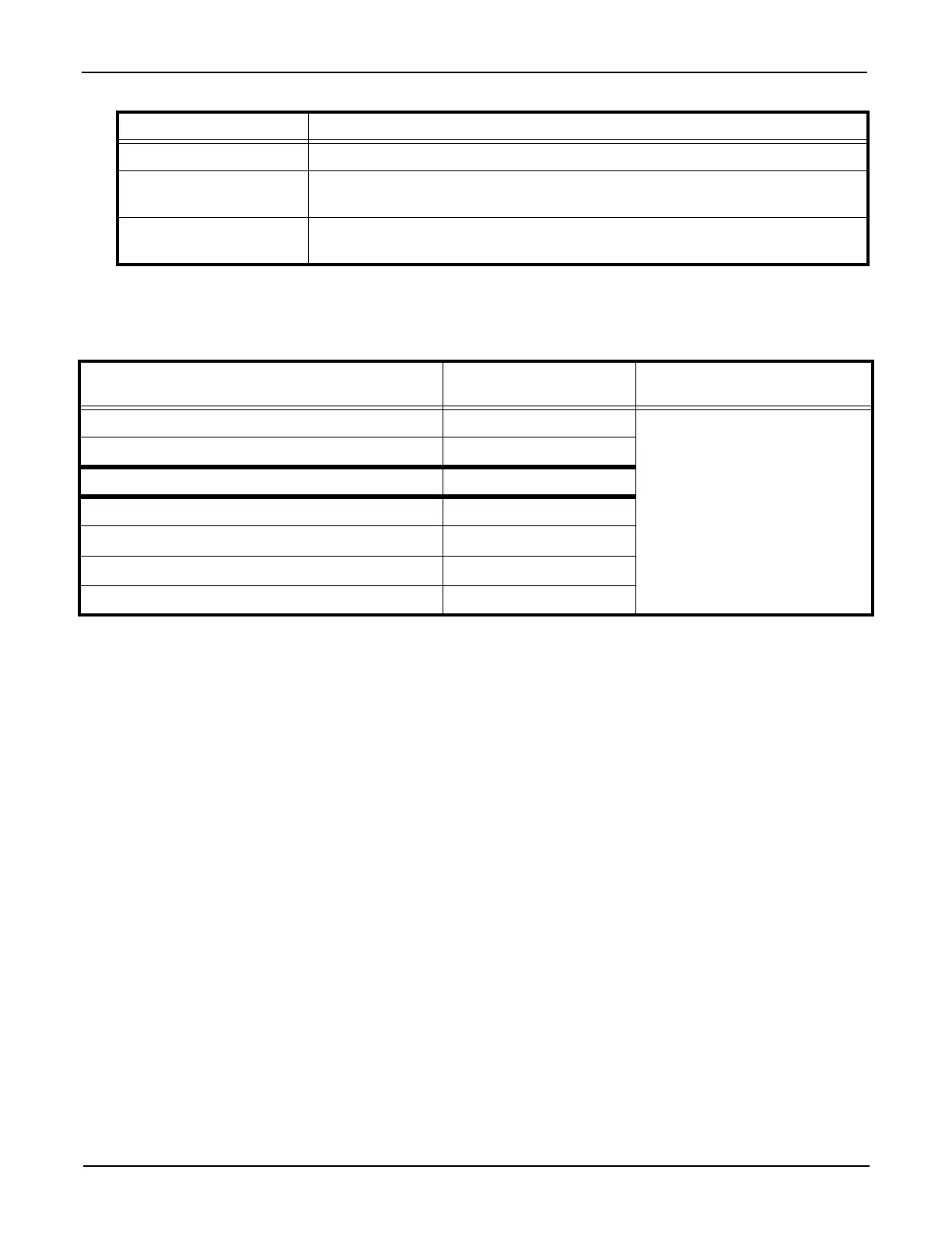
Table 2: Electrical Specifications
AUXILIARY OUTPUTS MAXIMUM CURRENT COMBINED MAXIMUM
CURRENT
LED for each door reader 25 mA (each)
1.1 Amps
Buzzer (BUZ) for each door reader 25 mA (each)
OUTPUTS MAXIMUM CURRENT
1 for Auxiliary Power (11.2 to 13.75 VDC) 450 mA
2 for Controlled Readers (11.2 to 13.75 VDC) 175 mA
2 for Controlled Readers (5 VDC) 175 mA
1 for Lock Output (11.2 to 13.75 VDC) 650 mA
Table 1: Technical Specifications
Specification Description