DN1769-1809
24
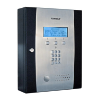
STEP 8: Connecting a 3rd Party Controller
The +V terminal voltage level is set by jumper JP9 (5V, 12V or EXT).
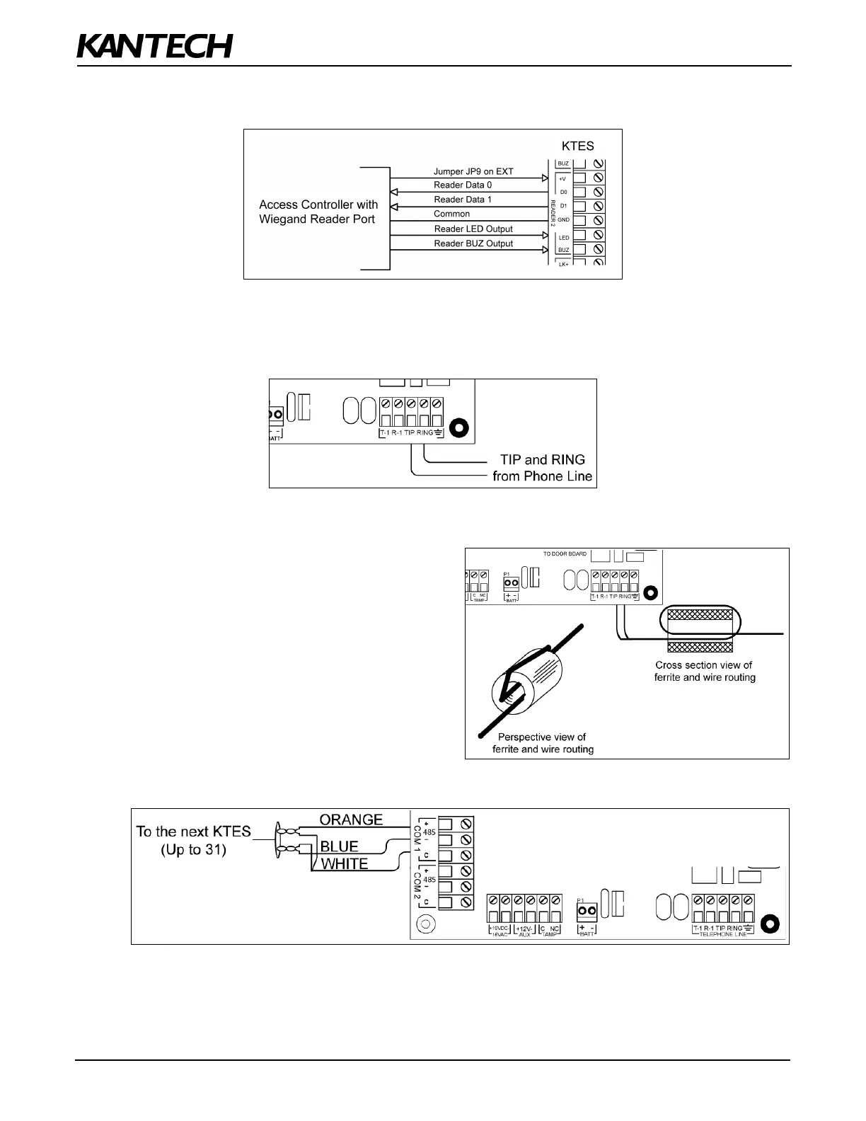
STEP 9: Connecting the Telephone Line
Connect the TIP (green) and RING (red) from the Phone Line to the TIP and RING terminals.
Note: The (T-1 and R-1) terminals can be connected to the local telephone.
STEP 10: Connecting the Telephone Line with the Ferrite (KTES-AUS Model for
Australia and New Zealand only)
Attach the ferrite as close as possible to the TIP and
RING terminals.
Connect the TIP and RING from the Phone Line to the
TIP and RING terminals.
Tie wrap the cable directly behind the ferrite.
Note: The (T-1 and R-1) terminals can be connected to
the local telephone.
STEP 11: Connecting the RS-485 (optional)