DN1769-1809
23
Kantech Telephone Entry System Installation Manual
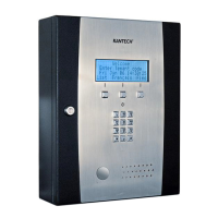
Resistors for all Inputs 5.6K Ohms (EOL or DEOL) (Optional)
The KTES has an on-board capability of monitoring 4 input points. Each onboard input is supervised with or
without end-of-line resistors (5.6K ohm). The maximum distance of one line is 600 m (2,000 ft) with AWG #22.
Inputs 1-2 are automatically assigned. The door contact is assigned to input 1 and the postal lock is assigned for
input 2. There is no obligation to follow these rules but this standard convention facilitates servicing.
DRY (without EOL resistor): In a simple NC dry contact configuration, the secure state is given when a short is
detected. The alarm state is given when the input is open. If the alarm switch is programmed as NO device, the
alarm state will be given when the input is shorted.
EOL (with EOL resistor): The secure state is given when a single resistor is detected. The alarm state is given
when the input is open or short.
DEOL (Double EOL Resistor): For NC device only, in a DEOL configuration, the secure state is given when a
single resistor is detected. The alarm state is given when two resistors in series are detected. The trouble state is
given when the input is shorted. The tamper state is given when the input is left open.
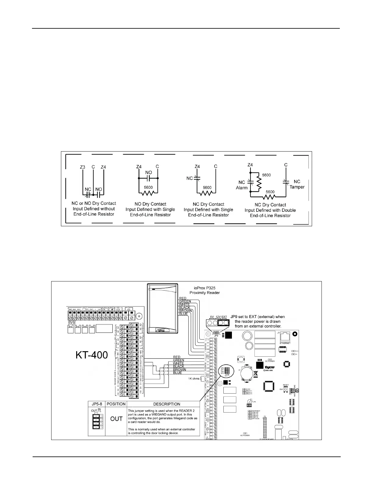
STEP 7: Connecting an External Controller
The distance between the reader and the KTES varies by reader type. Consult the installation manual for details.
Important: When you want the external controller to power the reader, the jumper JP9 must be put on external
(EXT) since the external controller will supply the +12 VDC to the reader connected on the READER 1
terminals.