DN1769-1809
22
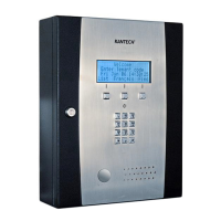
STEP 4: Connecting the Door Locking Device (DC Powered)
Connecting the Door Lock Device to LK+ and
LK-
Check for Local “magnetic lock” Regulations
The door locking device output is controlled according to
the end-user programmed parameters for allowing
access to or unlocking doors according to schedules and
access levels. The door locking device output can
operate DC powered locking devices such as an
electromechanical strike and can be configured to
operate fail-safe or fail-secure (normal or reverse action).
Note: Use 1 K ohm EOL (End-of-Line resistor) between LK+ and LK- terminals if not used.
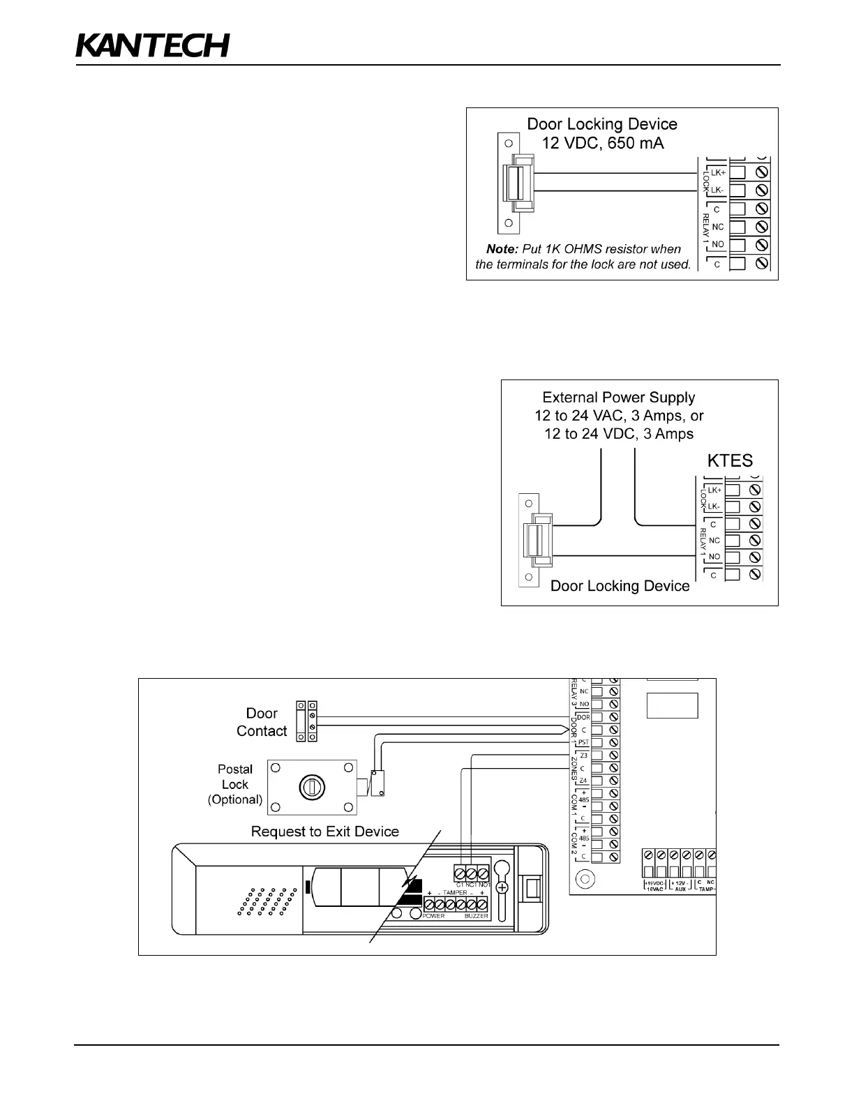
STEP 5: Connecting the Door Lock Device with an External Power Supply
Use one of the three relay terminals available to connect the
door locking device and the external power supply.
STEP 6: Hooking Up Inputs
Connect Devices to Inputs 1 to 4
Note: Onboard inputs can be defined with: none, single or double EOL (End-of-Line) resistor(s) according to your
settings with the VUI or with EntraPass.