132
NET/ROM or TheNET firmware), and a special serial cable to connect the KPC-3 to the
other TNC.
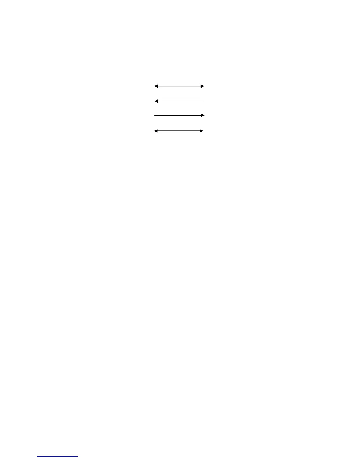
Construction of the serial cable is straightforward. Using two male DSUB-25 connectors,
connect pin 1 to pin 1, pin 2 to pin 3, pin 3 to pin 2, and pin 7 to pin 7.
KPC-3PMX (Ver. 9.1) KPC-3PMX (Ver. 9.1)
Frame ground 1 1 Frame ground
Transmit data 2 3 Receive data
Receive data 3 2 Transmit data
Signal ground 7 7 Signal ground
With the above cable assembled, the two KPCs with K-Net enabled, are free to
exchange network data over their respective serial ports.
Operation is probably very close to what you would imagine it to be. Each TNC must be
given a unique NETALIAS and NETCALL because they are separate nodes. They
should also be configured with the node parameters that are recommended in your
area. The serial cable functions as a "virtual radio circuit" for node-to-node
communication in the stack.
REMEMBER! The serial ports are talking to each other - the serial port mode parameter
must be set the same in both nodes (i.e. 9600, n, 8, 1).
The final step to activate this 2 port stack is to set the INTFACE command in each of
the TNCs to NET and to power them off and then back on.
Three Ports (One High-Speed and two 1200-Baud Ports)
A three port node stack consisting of a high-speed port and two 1200-baud ports can be
created by using a KPC-3 Plus modem with version 9.1 PROM installed and a KPC-
9612 Plus, also with the version 9.1 installed. Since the high-speed port of the KPC-
9612 Plus is capable of 4800, 9600, or 19200 baud operation, this set-up offers
tremendous flexibility in network configuration. As above, each of the K-Net nodes must
be programmed with a different NETALIAS and NET CALL and use the serial port cable
described above to tie them together. Now set the INTFACE command in each TNC to
NET and power them off and back on to complete the installation.
More than Three Ports
The two and three port stacks discussed above are relatively simple to cable together
since there is no contention for the serial port. Each node is free to broadcast and pass
data over the serial port "radio". Adding another node to the stack means that now there
needs to be a method to control access to the common serial port cable in order to
avoid data collisions. The K-Net node uses the RTS (Request To Send - pin 4) and CTS
(Clear To Send - pin 5) control lines of the serial port for this purpose.