8
安裝方法
Preparation before installation
HOW TO INSTALL
安裝前準備
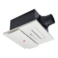
請於固定佈線與本產品主機間安裝觸點開距不小於3 mm的
“電源全極開關”(規 格必須不 低於250 V 13 A)及
~
漏電保護開關(洩漏電流在30 mA以下))。
電源 全極 開關(另 購)
固定 佈線
Install an all-pole switch with the contact separation not less
than 3 mm and specifications not lower than 250 V 13 A
~
and a leakage protection switch (with the leakage current
lower than 30 mA) between the fixed wring and the main
body of this product.
All-pole switch
(Need to be purchased)
Leakage protection switch
(Need to be purchased)
Fixed wiring
Main body
of this
product
漏電 保護 開關(另 購)
本產 品主 機
1. Connecting power cord
電源線的連接
Strand the core wire together after stripping,
then insert them into about 8 mm deep position
of the terminal block, ensuring that the part is
under the spring slice, and no copper core cord is
exposed outside. Make sure that the copper core
cords are fixed by screws reliably (the
.
recommended screw fixing torque is 0.49 N m)
(See Figure 2). Otherwise an electric shock may
be caused.
先將剝線後分散的銅芯線絞合在一起,然後伸入到端子
台約8 mm深,並確保其在彈簧片的下方,切勿出現銅
線外露現象。螺釘擰緊後,請確保銅線不易鬆脫(建議
.
螺釘鎖緊扭矩為0.49 N m),否則可能會導致觸電。
(右圖2)
電源線的絕緣膠不能破損,否則可能會導致觸電或短路。
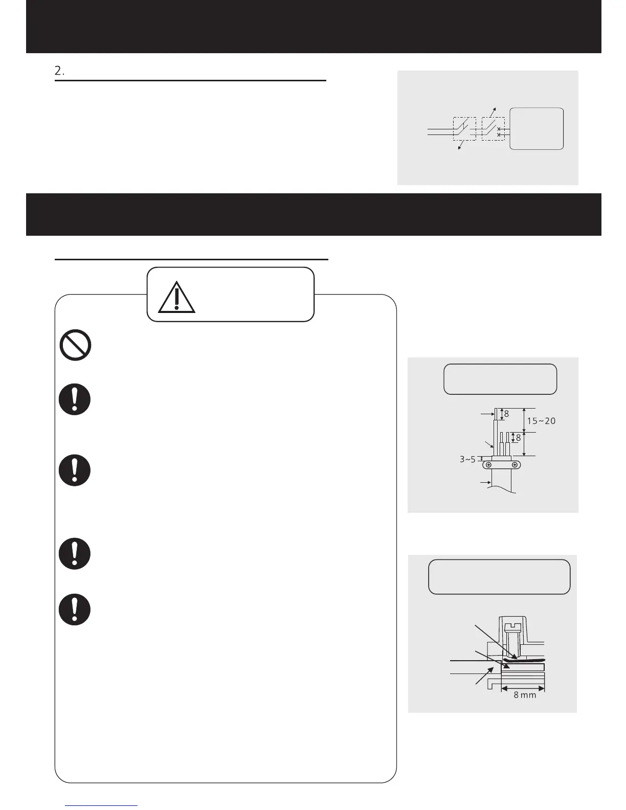
剝線長度,請按照剝線示意圖(右圖1)進行剝線,如剝線
過長,可能會導致產品短路。
電源線請選用60227 IEC 53型絞合軟線,導線的截面
2
積為3×1.5 mm 。
For the stripping length, please prepare
according to the wiring sketch (refer to figure 1).
If the stripping length is too long, it may cause
short circuit.
Do not damage the sheath of the power cord,
otherwise an electric shock or short circuit may
be caused .
Please select 60227 IEC 53 ordinary polyvinyl
chloride sheathed cord. Nominal cross-sectional
2
area of conductors is 3×1.5 mm .
警告
WARNING
安裝和使用時禁止拆卸電路板蓋板,否則可能會導致觸
電或起火。
To avoid electric shock or fire, do not remove the
PCB cover.
Wiring sketch
Terminal cutaway view
Conductor
Conductor
Insulation
Figure 2
Figure 1
Spring slice
Earth
Power cord
44±1
剝線示意圖
接線柱剝面圖
Unit: mm
單位:mm
電源線
接地引線
銅芯線
銅芯線
絕緣膠
彈簧片
圖2
圖1
安裝前事項
WORK BEFORE INSTALLATION