14
General
1
2
4
3
4
5
6
6
7
7
8
8
8
9
9
10
11
12
13
14 14
14
14
15
16
17
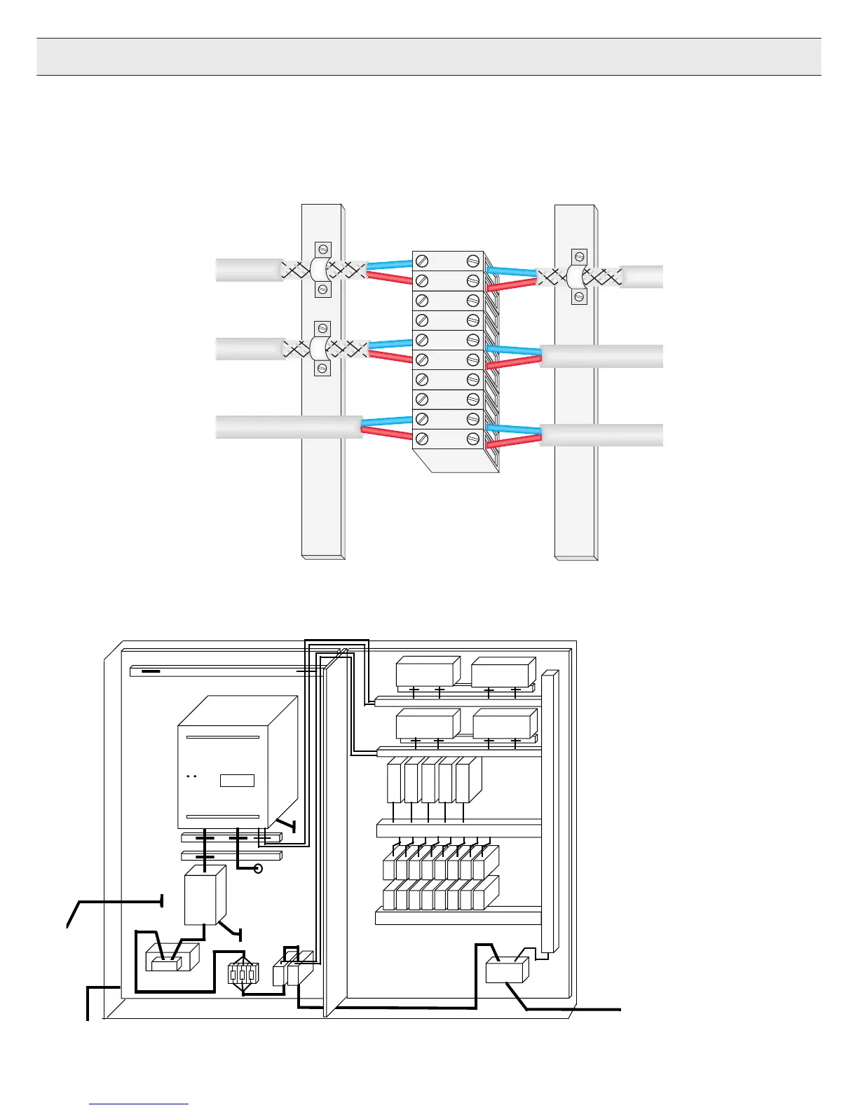
1. Cabinet
2. Sub-panel
3. EMI filter
4. Main voltage supply
5. Wires between EMI filter
and voltage supply
6. Motor wires
7. Control wires
8. Shield with clamps
9. Sub-panel is central
ground point
10. Main ground connection
11. Additional HF ground wire
12. Line choke
13. Low voltage power supply
14. PLCs or PCs
15. Inverter
16. Main supply fuse
17. Main supply contactor
1.5.12 Example control cabinet layout
Digital Signals
ground at both
ends
Analog signals
ground at one
end
Unshielded
signals
Use shield clamps to
make 360° contact on
shield.
1.5.11 Example shield connections
Local grounding point
within 8 inches of the
terminal connection

 Loading...


