43
4. Annex
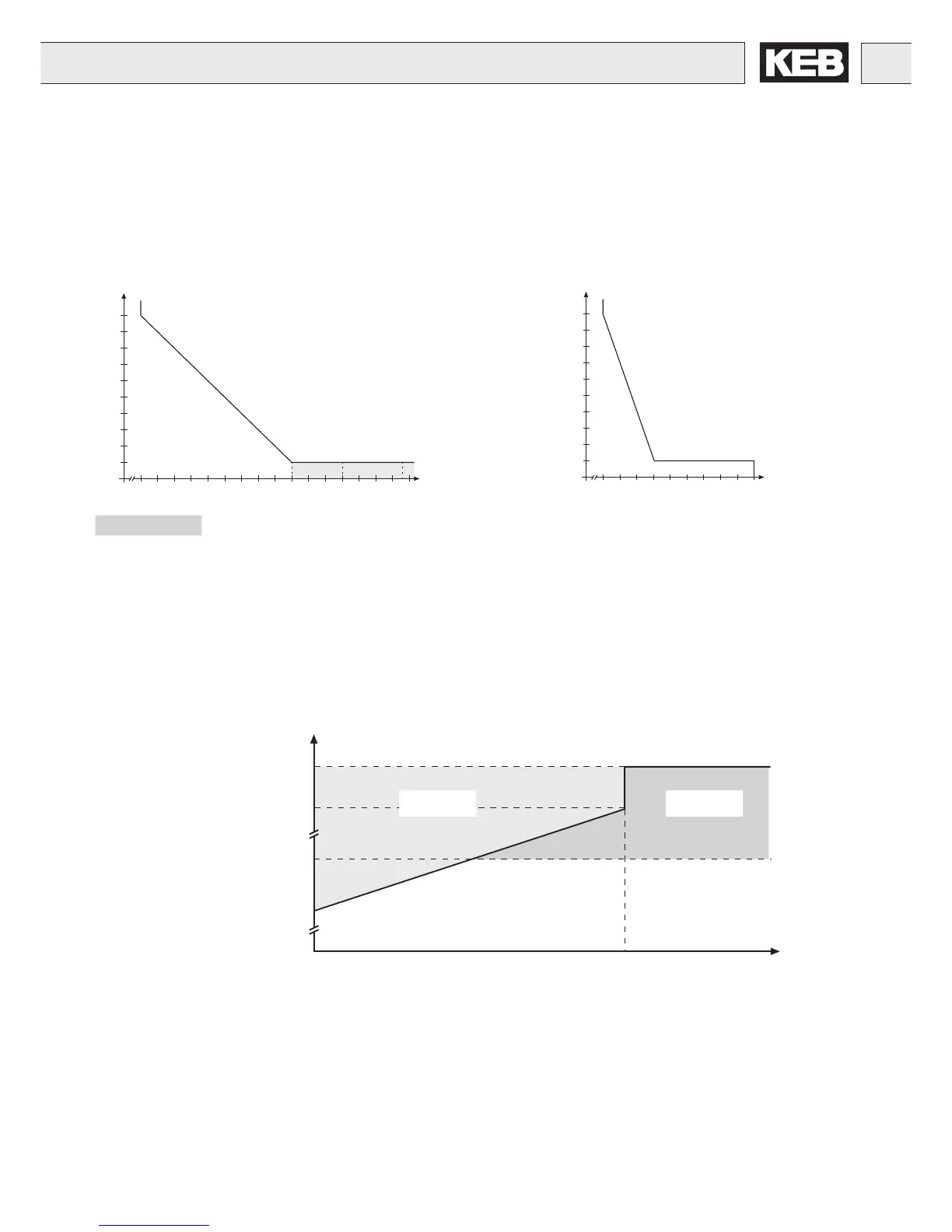
4.1 Overload Characteristic
4.2 Overload protection in the lower speed range
(only valid for F5-M and F5-S, stall current see technical data)
Load [%]
E.OL2 E.OL
Stall current
Short-time limit current
Min. frequency at con-
tinuous full load
OC-tripping current
If the permissible current is exceeded a PT1-element (τ=280ms) starts, after its sequence of operation
the error E.OL2 is triggered.
Start of overload
integrator at 105%
f [Hz]
Annex
Time [s]
Load [%]
30
60
90
120
150
180
210
240
270
300
0 105 110 115 120 125 130 135 140 145 150 160 170 180 190 200
210 220
The characteristic declines device-dependently in this range (see rating plate)
On exceeding a load of 105% the overload timer starts. When falling below the timer counts backwards.
If the timer achieves value for the overload characteristic that corresponds to the inverter, the error E.OL
is triggered.
Curve 1
30
60
90
120
150
180
210
240
270
300
0 105 110 115 120 125 130 135 140 145 150
Time [s]
Load [%]
Curve 2

 Loading...


