2
Technical Data
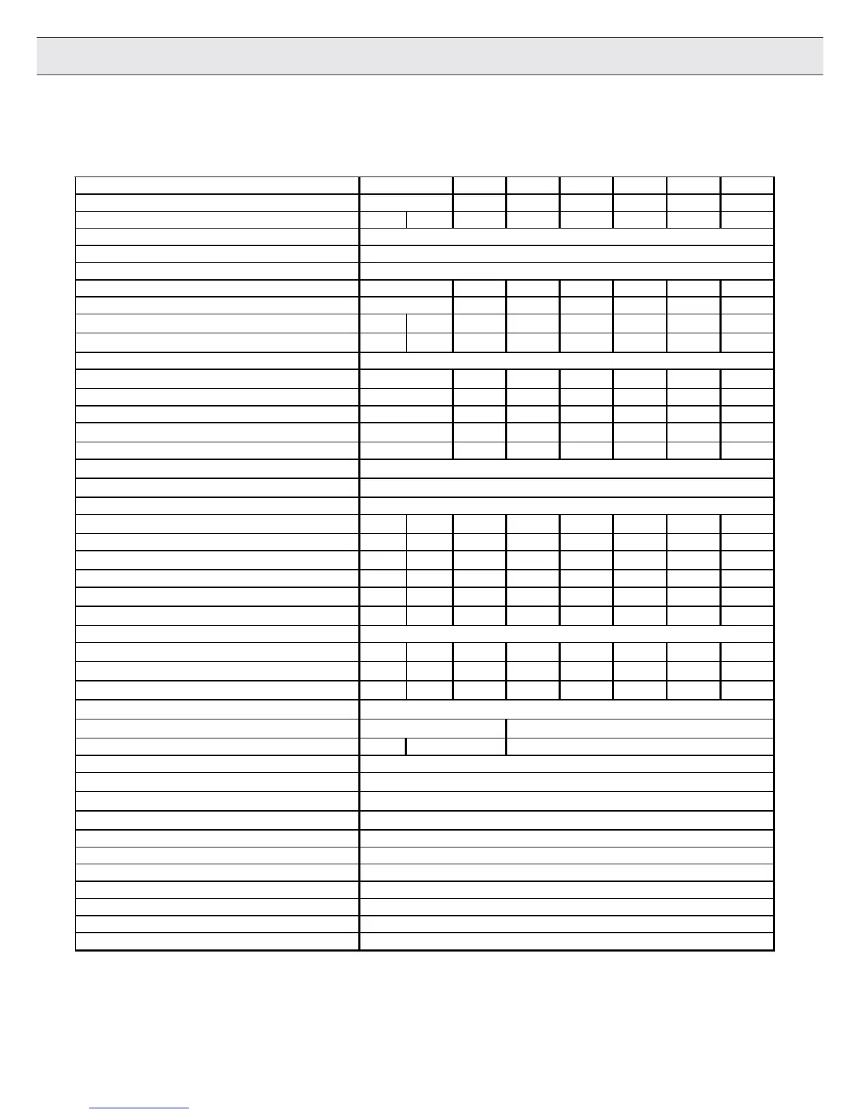
Technical Data 230V Class Continued
1) With the regulated systems F5-M as well as F5-S 5% must be subtracted as control reserve
3) The wire gauge is based on the maximum fuse rating, copper wire with minimum 75°C insulation rating, THHW or equivalent.
If branch circuit protection is selected based on rated input current, the wire size could be reduced.
4) This data is only valid for units with internal brake transistor GTR 7 (see "unit identification")
5) The maximum cable length is the same for all carrier frequencies.
6) Contact KEBCO for this specifications.
7) Rated operation means, rated input voltage, rated output current, and rated carrier frequency.
Inverter Size 15 16 17 18 19 20 21
Recommended Motor Power [hp] 15 20 25 30 40 50 60
Housing size GHHRRRRR
Input Ratings
Supply voltage [V] 180...260 ±0 (230 V rated voltage)
Supply voltage frequency [Hz] 50 / 60 +/- 2
Input phases 333333
Rated input current [A] 59 75 88 114 143 169
Recommended maximum input fuse
[A]
50 60 80 100 100 125 175 200
Recommended wire gauge
3)
[awg]
8643312/O3/O
Output Ratings
Rated output power
[kVA]
23 29 35 42 52 62
Rated motor power [kW] 15 18,5 22 30 37 45
Rated output current [A] 54 68 80 104 130 154
Peak current (30 seconds)
1)
[A]
99 126 150 172 225 270
Over current fault (E.OC) trip level [A] 119 135 162 207 270 315
Overload curve (see annex) 1
Output voltage
[V]
3 x 0...V input (3 x 0...255V
2)
)
Output frequency [Hz]
Generally 0 to 1600Hz (limited by control board and carrier frequency)
Rated switching frequency
[kHz]
4161688888
Maximum switching frequency [kHz] 4 16 16 16 8 8 8 8
Power loss at rated operation
7)
[W]
330 430 550 850 1020 1200 1400 1700
Stall current at 4kHz [A] 36 48 66 84 100 115 150 180
Stall current at 8kHz
[A]
- 48 66 84 100 115 150 180
Stall current at 16kHz
[A]
-486650 - - - -
Braking Circuit
Min. braking resistance
4)
Ohm]
16 13,6 8,8 5,6 5,6 4,7 3,9 3,0
Max. braking current
[A]
29 70 70 88 88 133 160 160
Installation Information
330
Tightening torque for terminal strip [in lb] 11 22 53
Environmental
Max. heat sink temperature TOH
[°C]
90°C / 194°F
Storage temperature
[°C]
-25...70 °C / -13…158°F
Operating temperature
[°C]
-10...45 °C / 14…113°F
Housing design / protection Chassis / IP20
Relative humidity max. 95% without condensation
Approvals
Tested in accordance with… EN 61800-3 /UL508C
Standards for emitted interference EN 55011 Class B / EN 55022 Class A
Standards for noise immunity IEC 1000-4-2 / -3 / -4 / -5/ -6
Climatic category 3K3 in accordance with EN 50178
Max. shielded motor cable length
5)
[ft] 165
3
17
11
42
72
88
46

 Loading...


