25
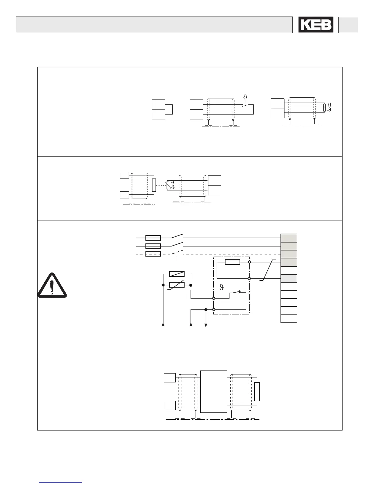
Connection of Power Circuit
T1
T2
T1
T2
Braking resistor
Braking module
Temperature sensor (PTC )
1650Ω...4kΩ tripping resistance
750Ω...1650Ω reset resistance
On F5 B/G units it is necessary to activate the function through
parameter CP.28.
T1
T2
F5-M/S:
Bridge, when no
sensor is connected
++
PB
T1
T2
Optional Connection
connect only when resistor has valid temperature
sensor, e.g. back mount resistors
GTR7
++
- -
+
-
PA
PB
External motor temperature sensor
(for all units)
Thermal switch
(NC-contact)
Don't install temperature sensor
wires with other control wires.
Must use double shield when running
temperature sensor wires with motor
wires
U
V
W
PB
L3
N/L2
X1A
T1
T2
--
L1
++
PA
PB
OH1
OH2
U
= 90°C
Braking resistor
with line side over
temperature cutoff
This is the only
way to turn off
voltage to the
resistor in the
event of failure of the
internal braking
transistor of the inverter.
24VDC or 120VAC contactor control voltage
Note: a NC thermal switch not PTC device on the resistor is required.

 Loading...


