29
Accessories
C
A
B
E
L
F
C
A
B
E
L
F
D
C
A
B
E
F
D G
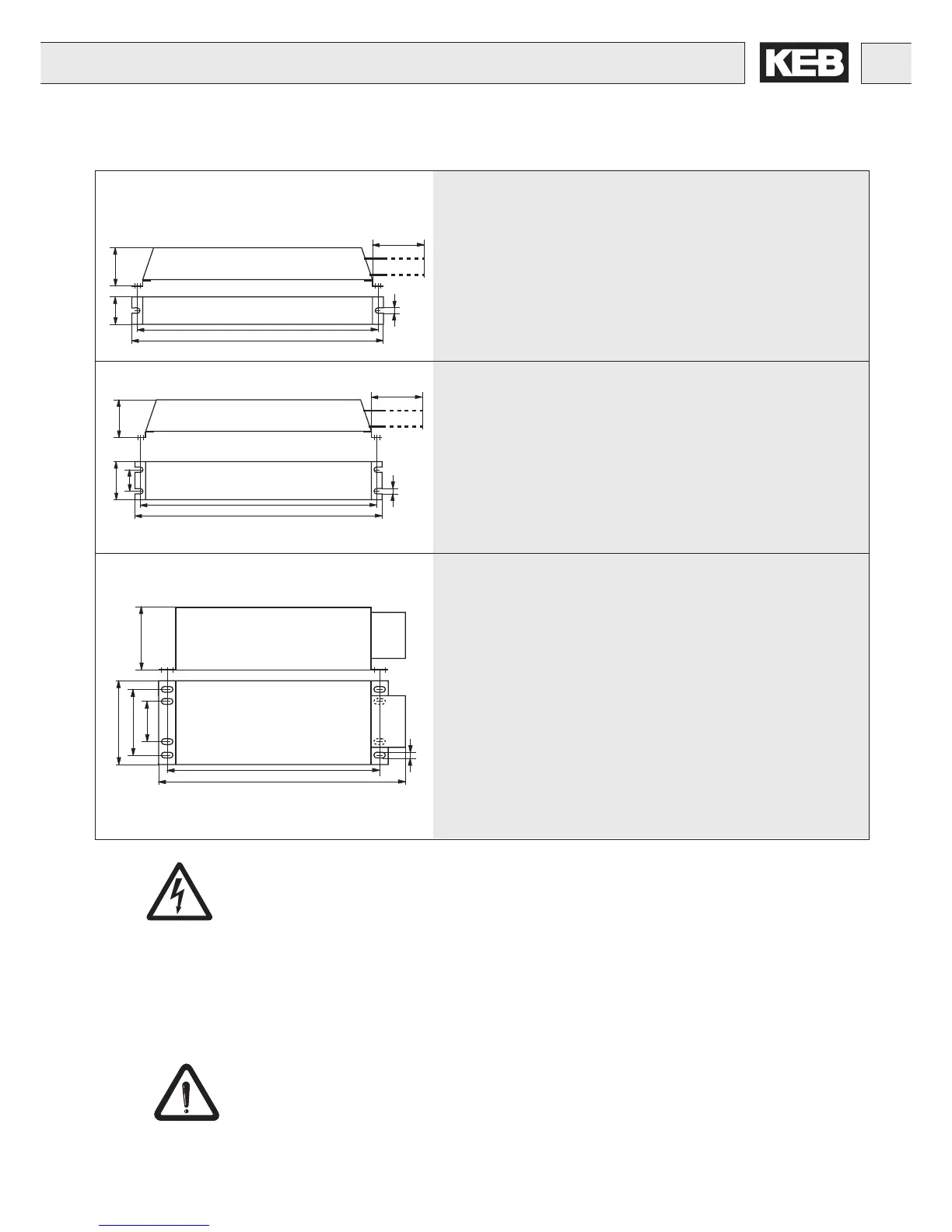
Part number A B C D E F L
07.BR.100-xxxx 0.95 6.5 1.57 - 5.67 0.20 39.0
09.BR.100-xxxx 0.95 9.5 1.57 - 8.74 0.20 39.0
10.BR.100-xxxx 0.95 11.8 1.57 - 11.22 0.20 39.0
12.BR.100-xxxx 1.0 11.8 3.15 - 11.22 0.20 39.0
13.BR.100-xxxx 1.0 15.75 3.15 - 15.16 0.20 39.0
14.BR.100-xxxx 1.0 15.75 3.15 - 15.16 0.20 39.0
15.BR.110-xxxx 2.48 14.6 3.78 - 13.98 0.20 39.0
16.BR.110-xxxx 2.48 18.5 3.78 - 17.91 0.20 39.0
Part number A B C D E F L
17.BR.110-xxxx 3.54 18.5 3.78 1.97 17.91 0.20 39.0
18.BR.110-1103 = 2 x 16.BR.110-1103
19.BR.110-xxxx = 2 x 17.BR.110-1073
20.BR.110-xxxx = 4 x 16.BR.110-1103
Part number A B C D E F G
18.BR.226-6203 10.5 24.1 4.57 9.45 20.71 0.25x0.4 6.93
19.BR.226-6153 10.5 24.1 4.57 9.45 20.71 0.25x0.4 6.93
20.BR.226-6123 10.5 24.8 8.7 9.45 20.71 0.25x0.4 6.93
21.BR.226-6103 10.5 24.8 8.7 9.45 20.71 0.25x0.4 6.93
22.BR.226-6866 10.5 24.8 10.7 9.45 20.71 0.25x0.4 6.93
23.BR.226-6676 10.5 24.8 10.7 9.45 20.71 0.25x0.4 6.93
24.BR.226-6506 = 2 x 21.BR.226-6103
25.BR.226-6436 = 2 x 22.BR.226-6866
26.BR.226-6386 = 1 x 22.BR.226-6866 + 1 x 23.BR.226-6676
27.BR.226-6336 = 2 x 23.BR.226-6676
28.BR.226-6226 = 3 x 23.BR.226-6676
29.BR.226-6176 = 4 x 23.BR.226-6676
30.BR.226-6136 = 5 x 23.BR.226-6676
Risk of Fire!
In order to safe guard against overheating braking resistors, it is absolutely necessary
to connect the thermal contact of the braking resistor to the inverter (See connection
to T1/T2 terminals on page 25). Overheating can have the following causes:
- ramps are too short
- too many stops per minute
- under dimensioned braking resistor
- input voltage too high, i.e. > 525VAC
- defective braking transistor in the inverter
If the braking transistor in the inverter fails, then the only means of
preventing the destruction of the resistor is by disconnecting the inverter
from the line via a contactor. The contactor can be opened using the fault
relay on the inverter.
Dimensions in inches
Dimensions in inches
Dimensions in inches
 Loading...


