10
Installation and Connection
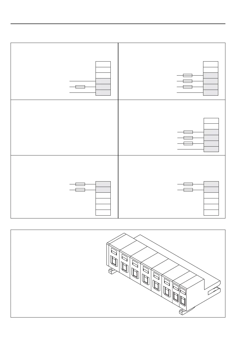
++
--
L1
PE
N/L2
L3
L1
PE
N
X1.A
Mains connection 230 V 1-phase
++
--
L1
PE
N/L2
L3
L1
PE
X1.A
L2
L3
++
--
L1
PE
L2
L3
L1
PE
X1.A
L2
L3
++
--
L1
PE
N/L2
L3
X1.A
+
-
++
--
L1
PE
L2
L3
X1.A
+
-
1 x 230 V AC
3 x 1,5 mm²
Mains connection 230 V 3-phase
3 x 230 V AC
4 x 1,5 mm²
Mains connection 400 V 3-phase
3 x 400 V AC
4 x 1,5 mm²
DC-connection 230 V-class
250...370 V DC
2 x 1,5 mm²
DC-connection 400 V-class
2 x 1,5 mm²
420...720V DC
3.3.3 Mains connection
3.3.4 Motor connection terminal strip X1.B
T2
T1
PB
PA
WV
U
PE
• PE Connection for earthing
• U, V, W Servo motor
• PA, PB Braking resistor
• T1, T2 Temperature sensor / switch
Protection
• Fuse 10 A slow-blowing or power protective
Power protective switch
(D-/K-characteristic at size 04)
• RCD (fault current protective switch)
Type A (at size 04) / else type A or B
• at DC-supply pay attention to the permissible
voltage range of the fuses
 Loading...


