12
1
2
3
4
5
6
7
8
9
10
11
12
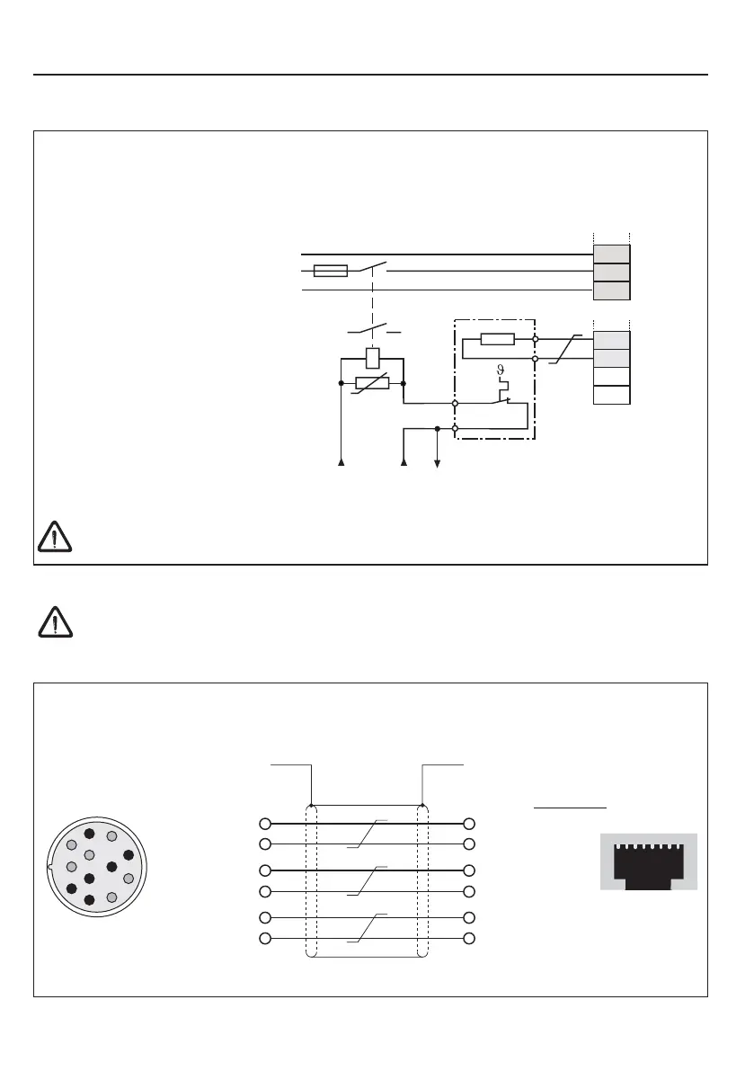
SIN - 1
SIN+ 10
REF - 5
REF + 7
COS - 2
COS+ 11
Housing
3.4.1 Resolver connection at KEB motors with connector X3A
3.4 Encoder interface connection
5 SIN - red
4 SIN+ blue
6 REF - yellow
3 REF + green
8 COS - pink
7 COS+ gray
Housing
Core color
18
The plugs may only be connected / disconnected when the inverter and supply voltage are
disconnected !
Servo motor
Resolver plug
Socket X3A
• Max. line length 50 m
PB
N
X1A
T1
T2
L
PA
PA
PB
OH1
OH2
U
K1
1112
X1B
PE
N
L
PE
3.3.6 Connection of a braking resistor with temperature monitoring in accordance with UL
• PA, PB Connection for braking resistor
• Technical data (see chapter 2.3)
• During clearing of the temperature monitoring the input voltage is switched off
• for additional protection in regenerative operation connect the auxiliary contacts 11
and 12 of the line contactor K1 (see 3.3.5)
Braking resistors can develop very high surface temperatures, therefor install as safe-to-
touch as possible.
230 or 24 V AC/DC
drive
at 24 V AC/DC
check tripping
 Loading...


