9
7
L1
L2
L3
++
--
E
Installation and Connection
3.3 Connection of Power Circuit
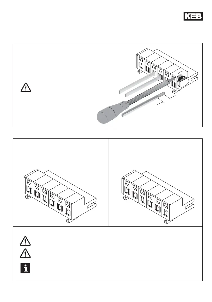
3.3.1 Wiring instructions
• Use a wire cross section of 1.5mm²
• strip 7mm
• optional use of wire-end ferrule
• After removing the screwdriver absolutely
check for a firm fit.
attach / remove terminal strip only at
tensionless state
3.3.2 Terminal Strip X1.A
PE
L1
N/L2
L3
++
--
PE
L1
L2
L3
++
--
Terminalstrip X1.A / 230 V class
• 230 V AC / 1-phase (L1/N)
• 230 V AC / 3-phase (L1, L2, L3)
• DC-Supply 250...370 V DC (++, --)
Terminalstrip X1.A / 400 V class
• 400 V AC / 3-phase (L1, L2, L3)
• DC-Supply 420...720 V DC (++, --)
Absolutely observe the connecting voltage of the KEB COMBIVERT. A 230V-unit
will be immediately destructed on a 400V-power supply.
Never exchange the mains and motor cables.
Some countries demand that the PE-terminal is directly connected to the terminal
box (not over the mounting plate).
 Loading...


