GB - 13
Technical Data of the 400 V Class
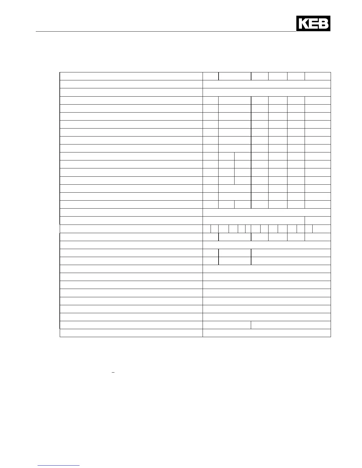
2.3 Technical data of the 400 V class
Unit size 23 24 25 26 27 28
Housing size U
Phases 3
Output rated power [kVA] 104 125 145 173 208 256
Max. rated motor power [kW] 75 90 110 132 160 200
Output rated current [A] 150 180 210 250 300 370
Max. short time current
1)
[A] 225 270 263 313 375 463
OC-tripping current [A] 270 324 315 375 450 555
Input rated current [A] 165 198 231 275 330 400
Max. permissible mains fuse gG
7)
[A] 200 315 315 400 450 550
Rated switching frequency [kHz] 8 4 8 4 4 2 2
Max. switching frequency [kHz] 8 8 8 8 8 8 4
Power dissipation at nominal operating [W] 1900 2000 2400 2300 2800 3100 3200
Power dissipation at DC operating [W] 1760 1830 2230 2100 2550 2800 2850
Standstill current at 4 kHz
2)
[A] 150 180 210 250 240 370
Standstill current at 8 kHz
2)
[A] 150 180 168 162.5 180 –
Standstill current at 16 kHz
2)
[A] – – – – – – –
Min. frequency at continuous full load [Hz] 3
Max. heat sink temperature 90°C 60/90°C
Cooling mode (L=air; W=water) W L W L W L W L W L W L W L
Motor cable cross-section
3)
[mm²] 95 95 95 120 150 240
Max. motor line length shielded [m] 50
Min. braking resistor
4)
[Ω] 5 4 2.2
Max. braking current
4)
[A] 160 200 380
Input rated voltage
5)
[V] 400 (UL: 480)
Input voltage range [V] 305…528 ±0
Input voltage at DC operation [V] 420…746 ±0
Mains frequency [Hz] 50 / 60 ±2
permitted mains forms TN, TT, IT
8)
,∆mains
9)
Output voltage
10)
[V] 3 x 0…Uin
Output frequency
11)
[Hz] 0 - max. 599
Overload characteristic (see annex A) 1 2
Cooling water content 600 ml
1) With the regulated systems 5% are to be subtracted as overmodulation capacity
2) Max. current before the OL2 function triggers (not in operating mode F5 GENERAL)
3) Recommended minimum cross section of the motor line for rated power and a cable length of upto 100 m (CU)
4) ThisdataisonlyvalidforunitswithinternalbraketransistorGTR7(see"unitidentication")
5)
At rated voltages > 460 V multiply the rated current with factor 0.86
7) Protection in accordance with UL see annex B
8) RestrictionswhenusingHFlters
9) PhaseconductorgroundedmainsareonlypermissiblewithoutHFlters
10) The voltage at the motor is dependent on the series-connected units and on the control method (see A.3)
11) The output frequency is to be limited in such way that 1/10 of the switching frequency is not exceeded. Units with
higher max. output frequency are subject to export restrictions and are only available on request.
The technical data are for 2/4-pole standard motors. With other pole numbers the inverter
must be dimensioned onto the motor rated current. Contact KEB for special or medium fre-
quency motors.
 Loading...


