GB - 31
Connection Power Unit
2.7.4 Temperature detection T1, T2
Parameter In.17 displays in high byte the installed temperature input of the inverter. The F5/
F6 COMBIVERT is delivered as standard with switchable PTC evaluation. A switchable KTY/
PTC evaluation is optionally available. The desired function is adjusted with Pn.72 (dr33 at
F6) and operates in accordance with the following table:
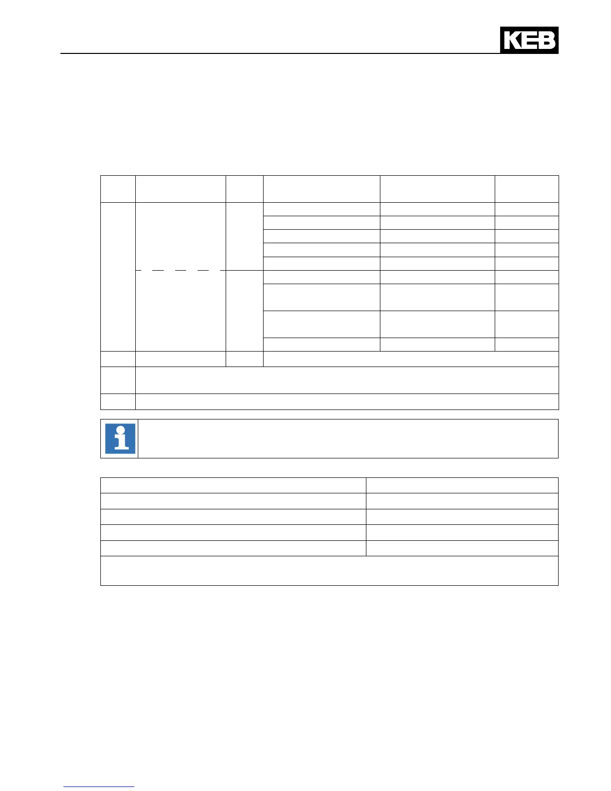
In.17
Function of T1,
T2
Pn.72
(dr33)
Resistance
Display ru.46
(F6 => ru28)
Error/warn-
ing
1)
5xh
KTY84
0
< 215 Ω
Detection error 253
x
498 Ω
1 °C
–
2)
1 kΩ
100°C
x
2)
1.722 kΩ
200°C
x
2)
> 1811 Ω
Detection error 254
x
PTC
(in accord-
ance with
DIN EN 60947-8)
1
< 750 Ω
T1-T2 closed
–
0.75…1.65 kΩ
(reset resistance)
T1-T2 closed
–
1.65…4 kΩ
(tripping resistance)
T1-T2 open
x
> 4 kΩ
T1-T2 open
x
6xh PT100 –
upon request
1)
The column is valid at factory setting. The function must be programmed accordingly
with parameters Pn.12, Pn.13, Pn.62 and Pn.72 for F5 in operating mode GENERAL.
2) Disconnection is depending on the adjusted temperature in Pn.62 (F6 => pn11/pn14).
Thebehaviouroftheinverterincaseoferror/warningisdenedwithparameters
Pn.12(CP.28),Pn.13(F6→pn12pn13/).
Dependent on the application the temperature input can be used for the following functions:
Function Mode(F5→Pn.72;F6→dr33)
Motor temperature display and monitoring KTY84
Motor temperature monitoring PTC
Temperature control for water-cooled motors 1) KTY84
General fault sensing PTC
1) If the temperature input is used for other functions, the motor temperature control at
water-cooled inverters can be done indirectly via the water cooling circuit of the inverter.

 Loading...


