GB - 36
Connection Power Unit
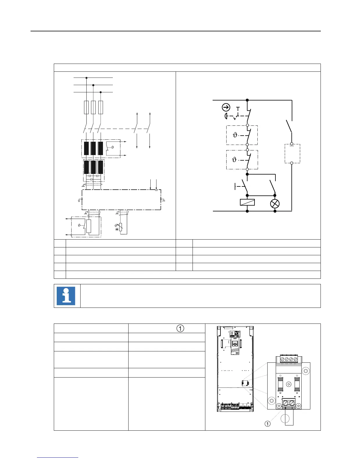
Braking resistor with over-heat protection without GTR7 monitoring
T1 T2
L1
L2
L3
K3
2
U V W
L1 L2 L3
1
4
3
6
5
12
11
14
13
G1
R1
+PA
PB
OH1
OH2
I10V
OH1
OH2
PE
DR1
HF1
F
R2
+24V
S2
I1
G1
K3
GND
S1
K3
11
12
H1
0V
R1
DR1
OH1
OH2
OH1
OH2
K3
13
14
K3 Line contactor with auxiliary contacts R1 Braking resistor with temperature switch
S1 Key for switch on R2 PTC/KTY84 sensor e.g. of the motor
S2
Emergency stop circuit braker for switch o
DR1
Mains choke with temperature switch (optional)
H1 Tripping control HF1 HF lter
G1 Inverter with programmable input I1
The gure serves only as an example and must be adjusted according to the appli-
cation.
2.7.6 External fan power supply
Terminal strip X1F
+
-
Terminals +, -
Voltage supply +24 Vdc ± 10 %
Current draw per
Module
2.5 A or 5.0 A
see technical data
Spare fuse(s) 3.15 A Type gG

 Loading...


