GB - 23
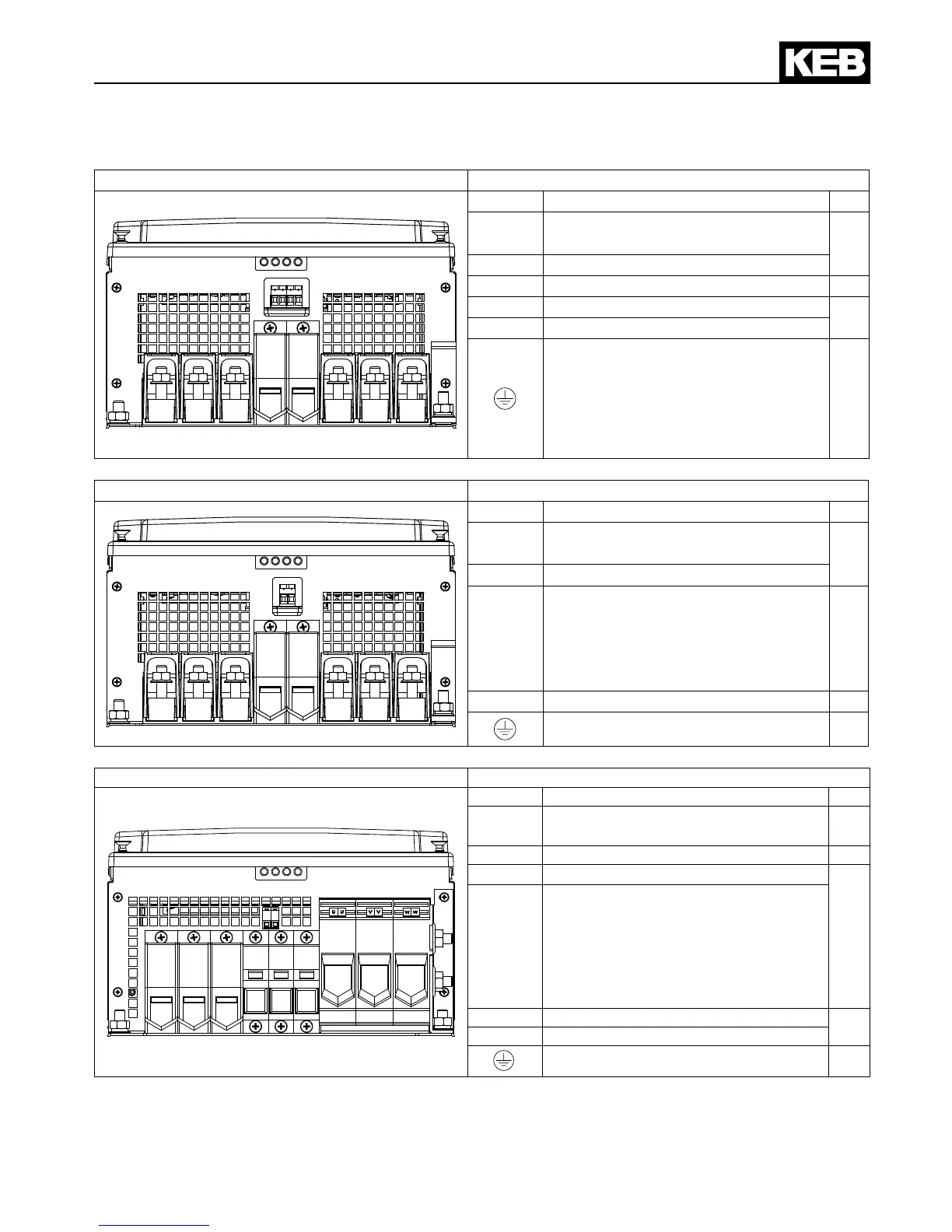
Terminals 400 V Class
Unit size 26…27 28 default with GTR7 Terminal in accordance with table 2.5
L1
L2
L3
PA
PB
U
V W
Name Function No.
L1, L2,
L3
3-phase mains connection
5
U, V, W Motor connection
PA, PB Connection for braking resistor
1
T1, T2 Connection for temperature sensor
3
K1, K2 GTR7 monitoring (optional)
Connection for shielding / earthing
5
Unit size 26…27 28 default with GTR7 Terminal in accordance with table 2.5
L1
L2
L3
+
-
U
V W
T1 T2
Name Function No.
L1, L2,
L3
3-phase mains connection
5
U, V, W Motor connection
+, -
DC link voltage
420…746 V DC (400V class)
Connection for braking module,
lterorDClinkcoupling
(unsuitable for DC supply)
1
T1, T2 Connection for temperature sensor
3
Connection for shielding / earthing
5
Unit size 27 advanced special version Terminal in accordance with table 2.5
L1 L2 L3
U
V W
+PA
-
PB
Name Function No.
L1, L2,
L3
3-phase mains connection
1
U, V, W Motor connection
2
PA, PB
Connection for braking resistor
4
+PA, –
DC link voltage
420…746 V DC (400V class)
Connection for braking module,
lter
or DC link coupling
(unsuitable for DC supply)
T1, T2 Connection for temperature sensor
3
K1, K2 GTR7 monitoring (optional)
Connection for shielding / earthing
5
 Loading...


