2000-903-01 Rev. C / October 2007 Return to Section Topics 1-3
Model 2000 Digital Multimeter Quick Start Guide Section 1: Introduction
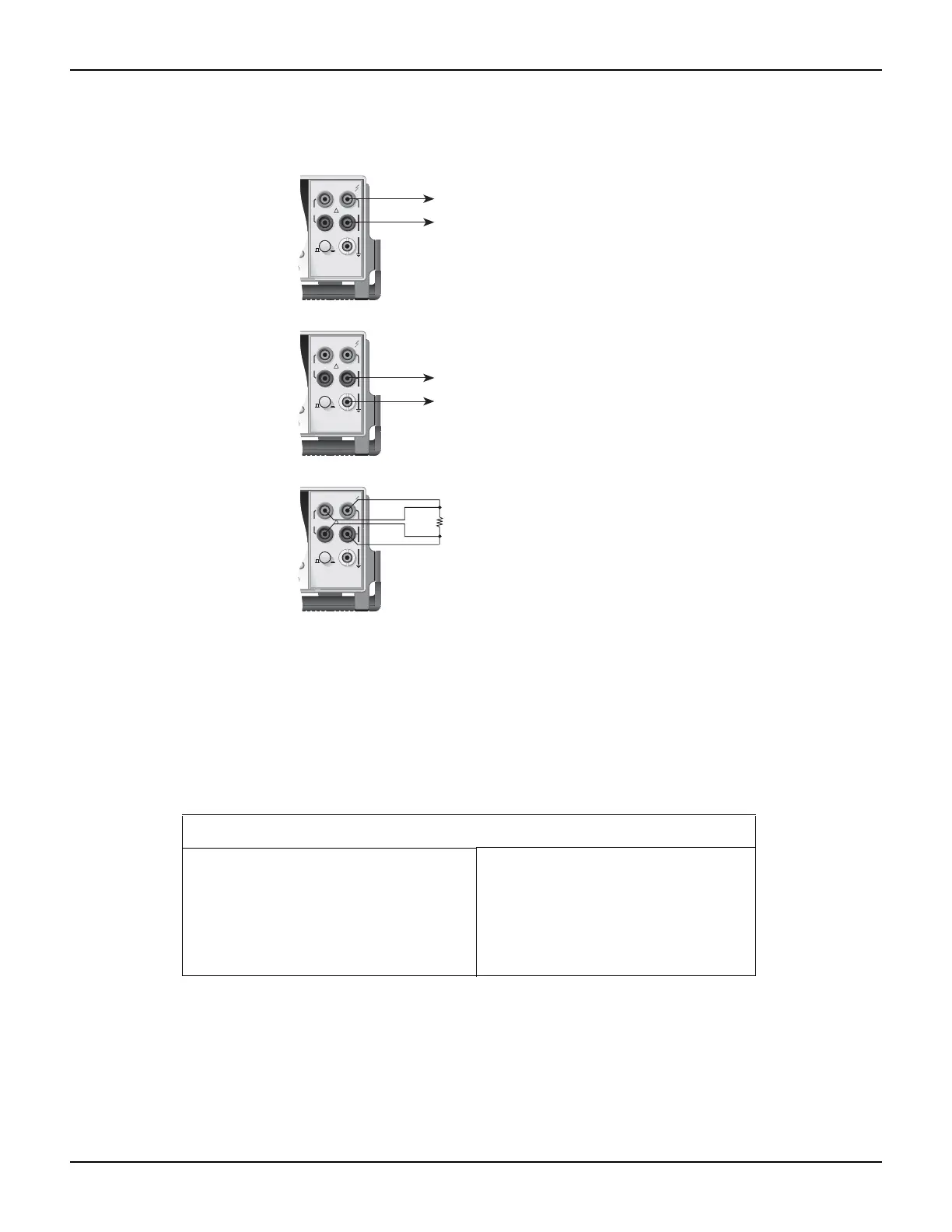
Figure 1-1
Basic measurement connections
For resistance measurements (¾2 and ¾4) greater than 100k¾, more stable readings can be
achieved by using shielding. Place the resistance in a shielded enclosure and connect the shield
to INPUT LO. Shielded cable should be used such that the shield (INPUT LO) encircles the other
cable conductor(s).
Maximum inputs for the Model 2000 are summarized in Table 1.
Basic measurement procedure
1. Connect the instrument as explained in “Instrument connection”.
2. From the function keys, select the desired measurement function.
3. Use the RANGE keys to select autoranging or a manual range. Pressing the AUTO range
key toggles autoranging. You can select a different range with the ▲ and ▼ RANGE keys.
4. Take a reading from the display.
Table 1-1
Commands to select sense mode
Function Maximum input
DCV 1000V peak
ACV 750V rms, 1000V peak, 8×10
7
V•Hz
DCI 3A dc, 250V
ACI 3A rms, 250V
FREQ (PERIOD) 1000V peak, 8× 10
7
V•Hz
METER
ANGE
!
F
500V
PEAK
FRONT/REAR
2A 250V
AMPS
HI
INPUT
LO
SENSE
Ω 4 WIRE
INPUTS
350V
PEAK
1100V
PEAK
AUTO
ANGE
R
Model 2000
Measure DCV, ACV,
Ω2, FREQ (PERIOD)
or TEMP *
* Temperature measurements are typically
performed through a thermocouple
scanner card, such as the Model 2001-TCSCAN.
See the User's Manual for details.
METER
ANGE
!
F
500V
PEAK
FRONT/REAR
2A 250V
AMPS
HI
INPUT
LO
SENSE
Ω 4 WIRE
INPUTS
350V
PEAK
1100V
PEAK
AUTO
ANGE
R
Model 2000
Measure
DCI or ACI
METER
ANGE
!
F
500V
PEAK
FRONT/REAR
2A 250V
AMPS
HI
INPUT
LO
SENSE
Ω 4 WIRE
INPUTS
350V
PEAK
1100V
PEAK
AUTO
ANGE
R
Model 2000
Measure
Ω4
R