Model 2500 Service Manual Routine Maintenance 3-3
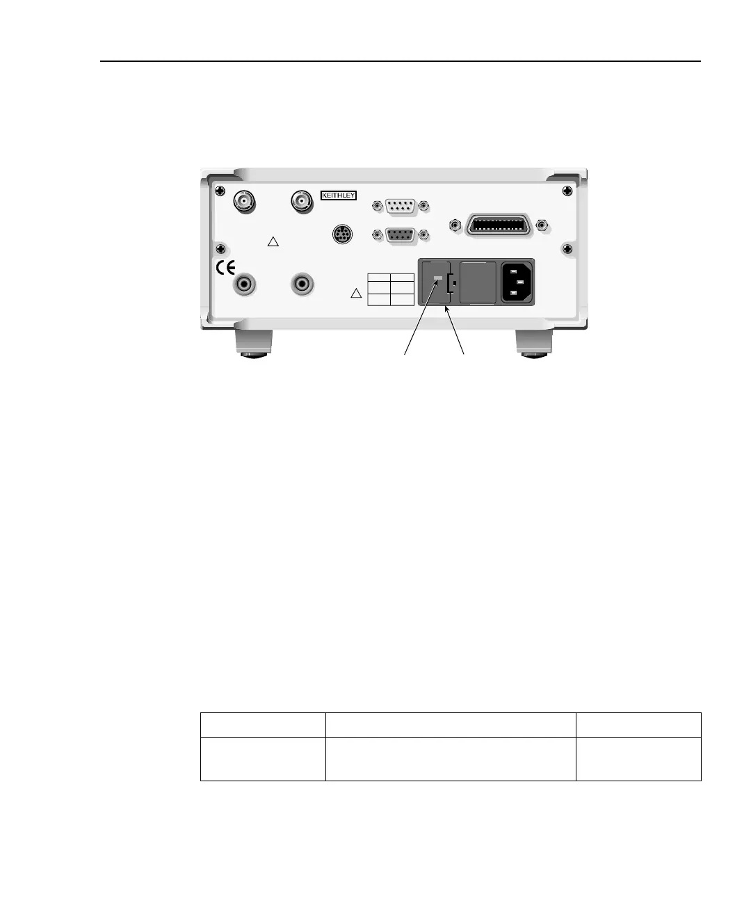
Figure 3-1
Model 2500 rear panel
Perform the following steps to replace the line fuse:
1. Using a small flat-blade screwdriver, carefully release the locking tab that secures
the fuse carrier to the power module.
2. Pull out the fuse carrier, and replace the fuse with the type specified in Table 3-1.
CAUTION To prevent instrument damage, use only the fuse type specified in
Table 3-1.
3. Reinstall the fuse carrier, pushing it in firmly until it locks into place.
NOTE If the power line fuse continues to blow, a circuit malfunction exists and must be
corrected. Refer to the troubleshooting information in Section 4 of this manual
for additional information.
Table 3-1
Power line fuses
Line voltage Fuse rating Keithley part no.
100V, 120V 0.630A Slo Blo, 250V, 5 × 20mm FU-106-.630
220V, 240V 0.315A Slo Blo, 250V, 5 × 20mm FU-106-.315
Model 2500
Line Voltage
Setting
WARNING: NO INTERNAL OPERATOR SERVICABLE PARTS, SERVICE BY QUALIFIED PERSONNEL ONLY.
CAUTION: FOR CONTINUED PROTECTION AGAINST FIRE HAZARD, REPLACE FUSE WITH SAME TYPE AND RATING.
120
LINE RATING
50, 60Hz
60 VA MAX
FUSE LINE
630 mAT
(SB)
315 mAT
(SB)
100 VAC
120 VAC
220 VAC
240 VAC
CAT I
MADE IN
U.S.A.
DIGITAL I/O
RS-232
TRIGGER LINK
INPUT
CHANNEL 1
INPUT
CHANNEL 2
VOLTAGE SOURCE
OUTPUT CHANNEL 1
VOLTAGE SOURCE
OUTPUT CHANNEL 2
RATINGS MAX
100V @ 20mA
COMMON
MODE
200V
RATINGS MAX
100V @ 20mA
!
!
IEEE-488
(CHANGE IEEE ADDRESS
WITH FRONT PANEL MENU)
Line Fuse

 Loading...


