Model 2500 Service Manual Troubleshooting 4-5
Overall block diagram
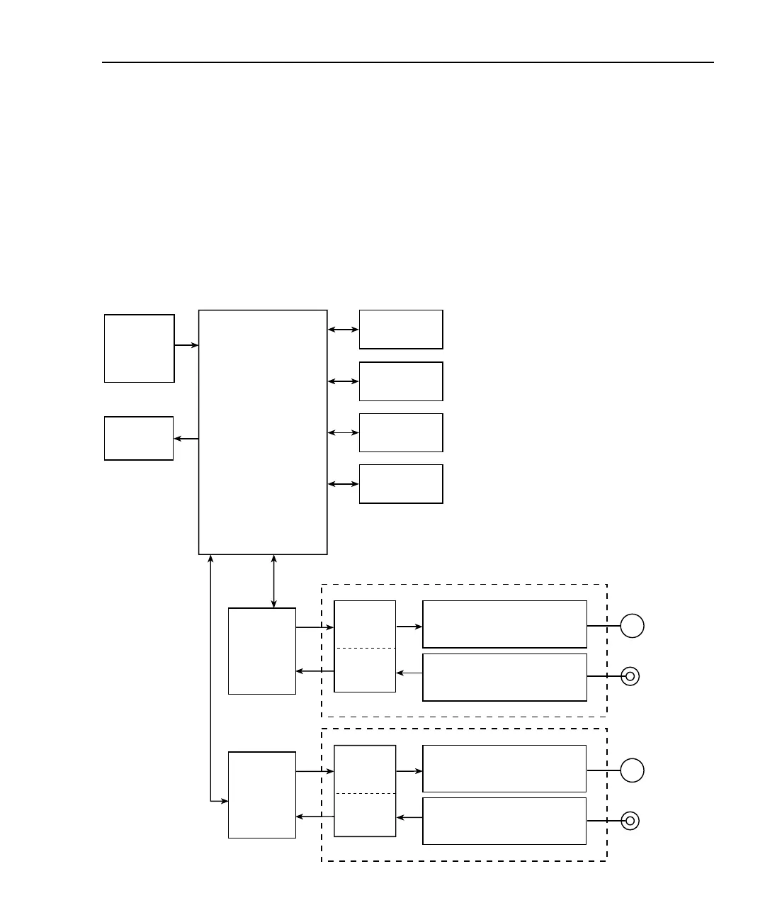
Figure 4-1 shows an overall block diagram of the Model 2500. Circuitry may be divided
into two general areas:
• Analog circuits — includes measurement circuits such as the I/V converter, mux,
and A/D converter, as well as voltage bias circuits.
• Digital circuits — includes the microcomputer that controls the analog section,
front panel, and GPIB and RS-232 ports, as well as associated interfacing circuits.
Figure 4-1
Overall block diagram
Front Panel
Keypad
2 Line VFD
GPIB
RS-232
Digital I/O
Trigger Link
OPTO
Interface
Channel 1
Voltage Source Channel 1
±10V, ±100V
20mA Max
I/V Converter Channel 1
(8 Current Ranges
2nA - 20mA)
OUTPUT 1
INPUT 1
I/V Converter Channel 2
(8 Current Ranges
2nA - 20mA)
Voltage Source Channel 2
±10V, ±100V
20mA Max
A/D
OPTO
Interface
OUTPUT 2
INPUT 2
MC68332
Microprocessor
Channel 2
A/D
D/A
D/A

 Loading...


