4-2 Troubleshooting Model 2500 Service Manual
Introduction
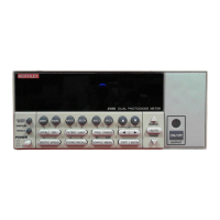
This section of the manual will assist you in troubleshooting and repairing the Model 2500
Dual Photodiode Meter. Included are self tests, test procedures, troubleshooting tables,
and circuit descriptions. Note that disassembly instructions are located in Section 5, and
component layout drawings are at the end of Section 6.
Safety considerations
WARNING The information in this section is intended for qualified service person-
nel only. Do not perform these procedures unless you are qualified to
do so. Some of these procedures may expose you to hazardous voltages
that could cause personal injury or death. Use caution when working
with hazardous voltages.
Repair considerations
Before making any repairs to the Model 2500, be sure to read the following
considerations.
CAUTION The PC boards are built using surface mount techniques and require
specialized equipment and skills for repair. If you are not equipped
and/or qualified, it is strongly recommended that you send the unit
back to the factory for repairs or limit repairs to the PC board replace-
ment level. Without proper equipment and training, you could damage
a PC board beyond repair.
• Repairs will require various degrees of disassembly. However, it is recommended
that the Front Panel Tests be performed prior to any disassembly. The disassembly
instructions for the Model 2500 are contained in Section 5 of this manual.
• Do not make repairs to surface mount PC boards unless equipped and qualified to
do so.
• When working inside the unit and replacing parts, be sure to adhere to the handling
precautions and cleaning procedures explained in Section 5.
• Many CMOS devices are installed in the Model 2500. These static-sensitive
devices require special handling as explained in Section 5.
• Whenever a circuit board is removed or a component is replaced, the Model 2500
must be recalibrated. See Section 2 for details on calibrating the unit.

 Loading...