Model 2500 Service Manual Troubleshooting 4-9
Digital circuitry
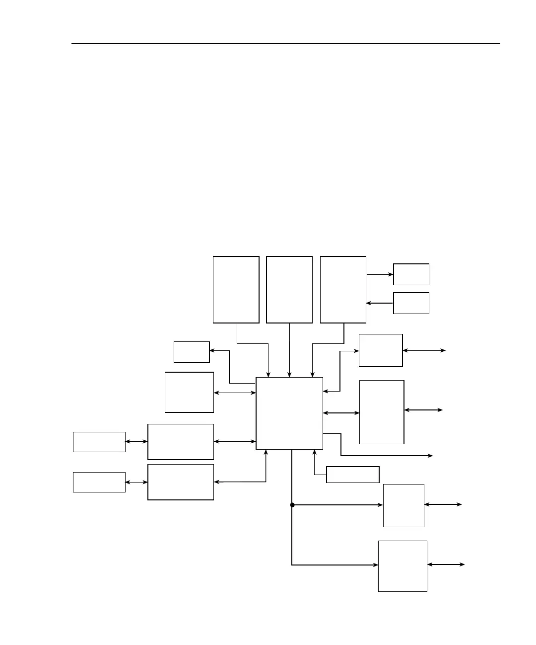
Refer to Figure 4-4 for the following discussion on digital circuitry.
The core digital circuitry uses a Motorola 68332 microcontroller running at 20MHz. The
memory configuration includes a flash EEPROM and a RAM. Flash ROM support allows
internal firmware upgrades using either the serial or GPIB port for downloading new firm-
ware. All calibration constants and the saved setups are stored in a separate serial
EEPROM.
External communication is provided via GPIB and serial interfaces. A 9914 GPIB IEEE-
488 with standard interface ICs are used for the GPIB, and an IC to provide the voltage
conversion for the RS-232 port.
Figure 4-4
Digital circuitry block diagram
ROM RAM
Reset
E PROM
2
Channel 1
OPTO Interface
Microprocessor
Serial
Interface
GPIB
RS-232
Interface
IEEE-488
Interface
To Display
Board Controller
Trigger
Digital I/O
Trigger
Link
Digital
I/O
32.768KHz
Channel 2
OPTO Interface
Front
Panel
Controller
Channel 1
Channel 2
VFD
Keypad

 Loading...


