System SourceMeter® Instrument Reference Manual Section 2:
2600BS-901-01 Rev. B / May 2013 2-11
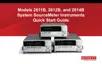
3. Digital I/O
2601B/2602B/2611B/2612B/2635B/2636B
Female DB-25 connector. Use a cable equipped with a male
DB-25 connector (Keithley Instruments part number CA-126-1).
Pins provided: Fourteen digital input or output pins, seven GND
pins, and three +5 V pins.
The Models 2601B and 2602B have an output enable pin. The
Models 2611B, 2612B, 2635B, and 2636B have an interlock pin.
Pins provided: One output enable pin, seven GND pins, and
three +5 V pins. The digital input and output pins are not
available on the Model 2604B.
Pins provided: One interlock pin, seven GND pins, and three
+5 V pins. The digital input and output pins are not available on
the Models 2614B and 2634B.
4. IEEE-488
Connector for IEEE-488 (GPIB) operation. Use a shielded cable, such as the
Keithley Instruments Model 7007-1 or Model 7007-2.
5. LAN
RJ-45 connector for a local area network (LAN). The LAN interface supports
Auto-MDIX, so either a CAT-5 cross-over cable (provided), or a normal CAT-5
straight-through cable (not provided) can be used.
6. USB port
This USB-2.0 receptacle (Type B) located on the rear panel is used to connect
the instrument to a computer. You can use this connection to send commands to
the instrument.
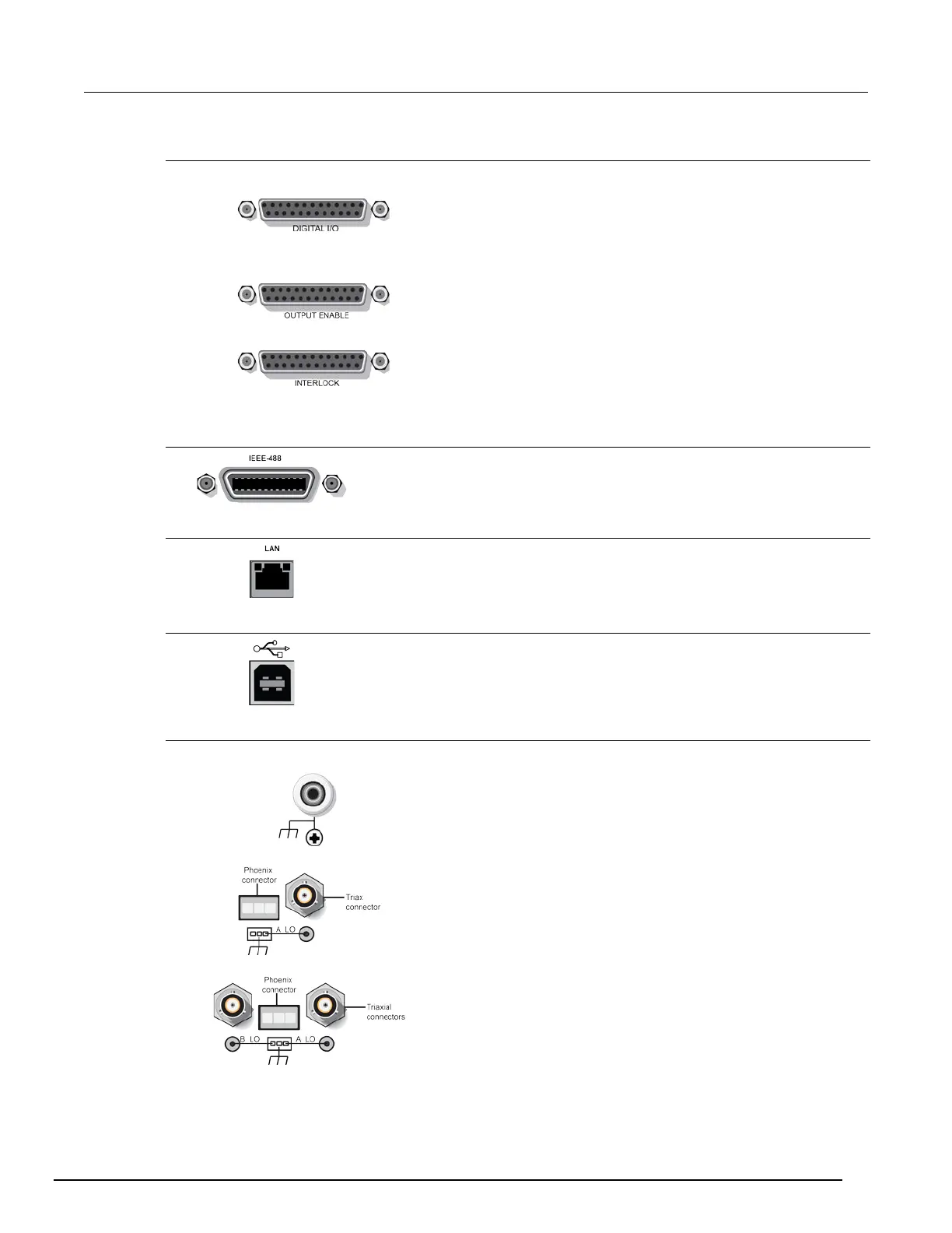
7. Ground
2601B/2602B/2604B/2611B/2612B/2614B
Ground jack for connecting output HI or LO to chassis ground.
Ground screw for connections to chassis ground.
Triaxial connector on ground module.
Phoenix connector on ground module.
 Loading...