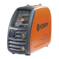
Do you have a question about the Kemppi Minarc Evo 150 and is the answer not in the manual?
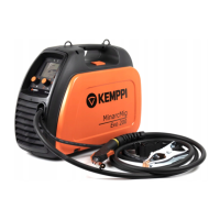
Details the technical specifications for Minarc Evo 150 and 180 models.
Illustrates the electrical wiring connections for the Minarc Evo 150/180 welding machine.
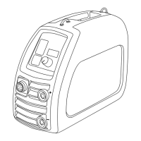
Identifies the main internal components of the Minarc Evo welding machine.
Details the structural layout of the Z001 main circuit card.
Details the structural layout of the A001 control card.
Describes the functions of the Z001 main circuit card and its components.
Describes the functions of the A001 control card and its features.
Details the programming capabilities and limitations of the control card.
Explains the procedure for calibrating the welding machine after component replacement.
Describes the buttons and LEDs used for entering and navigating calibration mode.
Lists and describes the various parameters used during the calibration process.
Provides a detailed step-by-step guide for calibrating the machine.
Outlines the methods for testing various components and circuits of the machine.
Details specific tests for the Z001 main circuit card components.
Describes testing procedures for the input rectifier and PFC circuit diodes.
Details how to test the IGBT module diodes using a multimeter.
Explains how to test the secondary rectifier diodes.
Details test points and expected voltages on the Z001 main circuit card.
Describes how to test the overheat protection mechanism involving PTC and NTCs.
Details troubleshooting and testing procedures for the A001 control card.
Explains how to test the cooling fan's operation and power supply.
Notes that low voltage tests cannot be performed on the Minarc Evo 150.
Covers safety tests, including PE conductivity, and precautions.
Provides guidelines for installing power components like modules and resistors, including torque specs.
Details the installation of rectifier/PFC and IGBT modules on the Z001 card.
Describes the installation of the secondary rectifier, including heat sink and torque specifications.
Outlines the final testing procedures after repair, including load tests and test welds.
Explains how to perform load bank tests to verify machine performance.
Emphasizes the importance of test welding for final verification of repairs.
| Input Frequency | 50/60 Hz |
|---|---|
| Duty Cycle @ 150 A | 30 % |
| Open Circuit Voltage | 85 V |
| Welding Process | MMA, TIG |
| Protection Class | IP23S |
| Input Voltage | 230 V |
| Output Current Range | 10 A / 150 A |
| Output (TIG) | 150 A |
| Welding Range (MMA) | 10 A / 140 A |
| Welding Range (TIG) | 10 A / 150 A |
| Electrode Sizes (MMA) | 1.5 - 3.25 mm |