17
Kemppi Oy
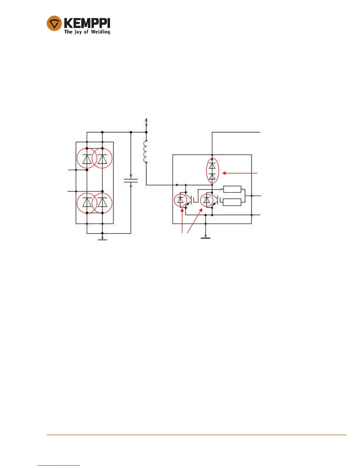
4.3.1.1. Input rectifier and PFC circuit
Mains supply voltage must not be connected during the rectifier/PFC module diode measuring.
In many cases of primary side failures input rectifier or the PFC circuit diodes may be broken. Rectifier
diodes can be measured one by one, but PFC circuit diodes only in two groups, because they are
internally connected parallel and in series. Two diodes between the PFC IGBT collector and emitter are in
parallel with IGBTs and the other two diodes are in series from PFC input to the DC-link positive.
Check the diodes using a multimeter diode function to measure their threshold voltage. Diodes must be
measured both forward bias and reverse bias condition to make sure they are satisfactory. See the
following pictures and table to make all the necessary measurements.

 Loading...