Do you have a question about the Kenwood PW-A series and is the answer not in the manual?
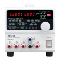
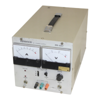
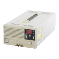
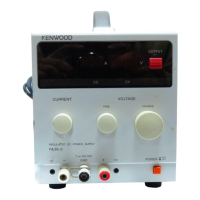
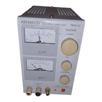
Details general operating parameters and physical characteristics of the PW-A series.
Describes the functionality of the YB option for quick output voltage descent.
Outlines specifications related to the remote sensing terminal functionality.
Details communication protocol for the IF-40RS interface.
Details communication protocols for IF-40GU (GP-IB) and USB interfaces.
Provides a general overview of the PW-A power supply unit's architecture and function.
Explains the purpose and operation of the optional IF units.
Describes the function of the input unit for quick voltage descent.
Details the circuit blocks and components within the amplifier unit.
Explains the digital control circuit, interfaces, and components of the CPU unit.
Lists the necessary instruments for performing calibration and adjustments.
Guides on setting the correct ID for adjustment mode based on the model.
Details the procedure for adjusting voltage and current output settings.
Provides a table showing connector wiring configurations for different models.
Shows component and pattern layouts for the power supply unit PCBs.
Displays component and pattern layouts for the input unit PCB.
Shows component and pattern layouts for the panel unit PCB.
Displays component and pattern layouts for the interface unit PCB.
Shows component and pattern layouts for the CPU unit PCB.
Displays component and pattern layouts for the amp unit PCB.
| Brand | Kenwood |
|---|---|
| Model | PW-A series |
| Category | Power Supply |
| Language | English |