6
4
SET PANEL
1
2
3
4
5
5
5
6
6
7
8
9
5
8
10
10
6
10
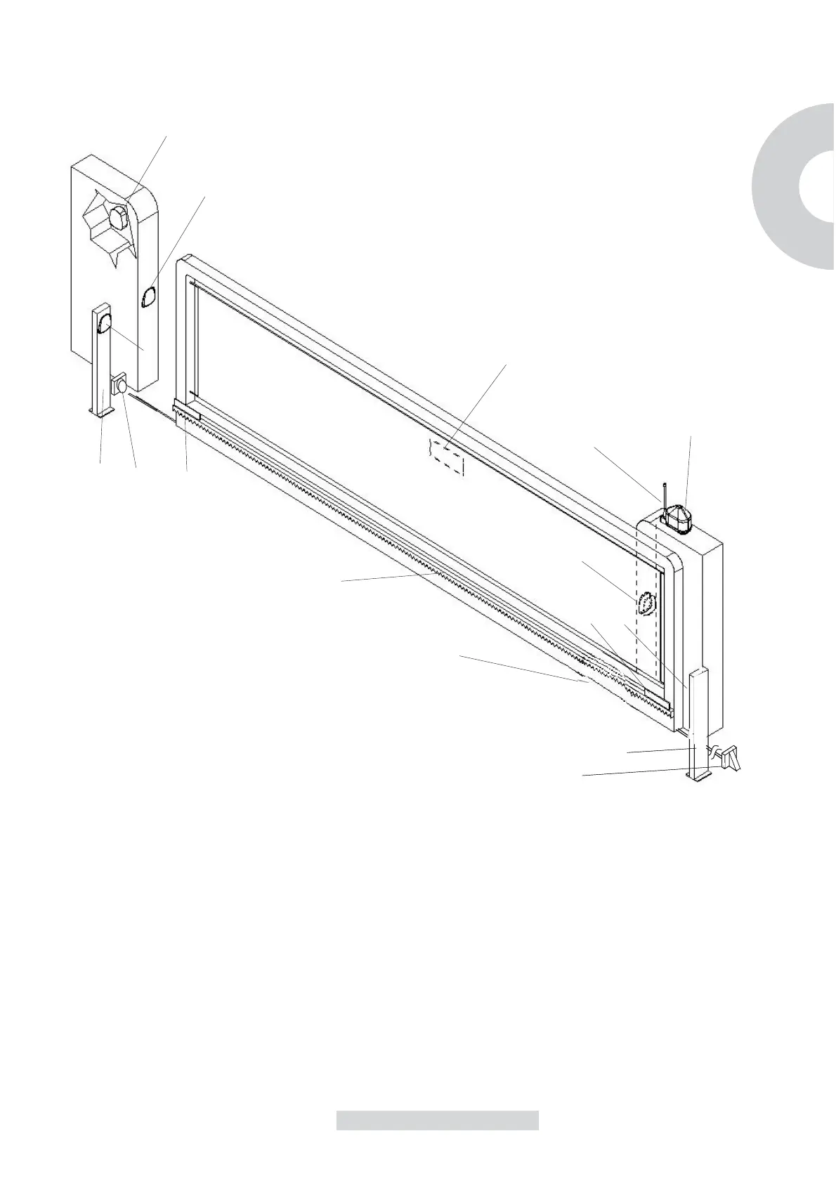
1 Gear-motor
2 Flash-light
3 Antenna.
4 Key selector
5 Photocell
6 Small columm
7 Rack
8 Limit switch
9 Warning sign
10 Stop locks
PREVIOUS INSPECTIONS
Before the installation starts, we suggest to carry out following inspections and
operations:
1_The gate framework must be strong and suitable.
2_The gate must not show too many sideways slide skids during the running.
3_The system of wheels/lower rail and roller/upper runner must work without too
many frictions.
4_To avoid the gate derailment you must install the stop beats of the sliding,
whether at the opening or closing, and a second upper roller/runner in full
observance of the current law.
5_Remove any manual lock in the beforehand gates.
6_Take on the gate bottom the feed raceway of the feeding cables (Ø25-50mm)
and of external connection (photocell, flash-light, key selector, etc...).
GB
7_System must be protected by a bipolar switch with limit of 30mA.
 Loading...