LIMIT SWITCH FIXING
The gate has to be equipped with stop locks at the opening and closing, which
prevent the gate derailment.
The stop lock position must assure that the limit switch brackets don’t collide with the
pinion gear.
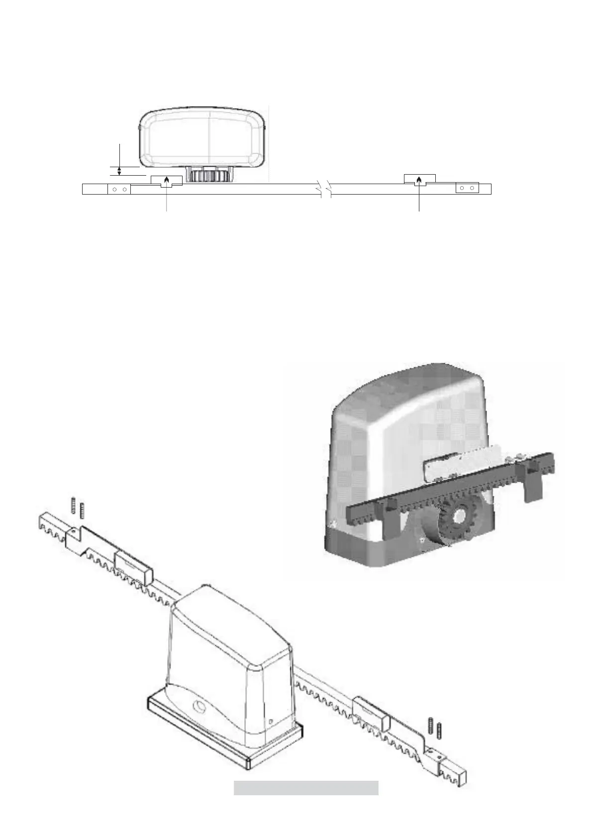
Fasten the limit switch bracket through the dowels (fig.11).
Put limit switch bracket in the way that the indicated point (S) on picture 10 will be on the centre
of pinion. Distance you must keep between motor and
fig.11
9
S
Max 10 mm
S
Fig.10
S
magnet must be between 5 and 10 mm.
in case limit switches are not detected by the control unit, we advise users to turn both
magnets by 180° on the horizontal metal brackets on which magnets are fixed.
 Loading...