Keyscan Inc. A Member of the Kaba Group
CIM 0
Jumper ON J4
COMMON AUX INPUTS - E
17 18 19 20 21 22 23 24
IOCB (COM1)
RX
TX
CPB/CB COMMS
(COM4)
H2
TD1
RD1
TD2
RD2
GND
RTS
CTS
GND
RTS
CTS
B3 B2 B1B0
Diag
J2
RESET
-
CAN2
+
EGND
-
CAN1
+
GND
V +
(+12V)
SCKT1
PC106x
J1
J7
J8
J6
J5
CAN2
CAN1
1 2 1 2 1 2 1 2
Rx-COM
COM
CAN CAN-Tx
J3
J4
J9
J12
Power
Good
Fault
HDR1
J10
J11
COMMON AUX INPUTS - E
17 18 19 20 21 22 23 24
IOCB (COM1)
RX
TX
CPB/CB COMMS
(COM4)
TD1
RD1
TD2
RD2
GND
RTS
CTS
GND
RTS
CTS
B3 B2 B1B0
Diag
J2
RESET
-
CAN2
+
EGND
-
CAN1
+
GND
V +
(+12V)
SCKT1
PC106x
J1
J7
J8
J6
J5
CAN2
CAN1
1 2 1 2 1 2 1 2
Rx-COM
COM
CAN CAN-Tx
J3
J4
J9
J12
Power
Good
Fault
HDR1
J10
J11
TD1
RD1
TD2
RD2
GND
RTS
CTS
GND
RTS
CTS
B3 B2 B1B0
Diag
J2
RESET
-
CAN2
+
EGND
-
CAN1
+
GND
V +
(+12V)
SCKT1
PC106x
J1
J7
J8
J6
J5
CAN2
CAN1
1 2 1 2 1 2 1 2
Rx-COM
COM
CAN CAN-Tx
J3
J4
J9
J12
Power
Good
Fault
HDR1
J10
J11
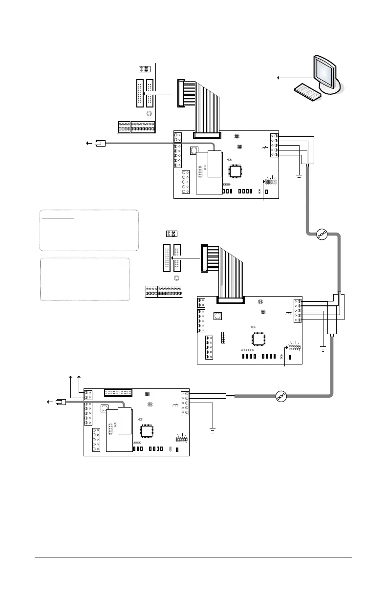
CIM 0
CIM 1
CIM-LINK
Termination Jumpers ON
CAN2 - J7 & J8
Connect EGND
terminal on all
CIMs to ground
lugs in ACU metal
enclosures.
CAT 5
CAN Bus
H2
KI-00491E-10-12
CAT 5
CAN Bus 2
Termination Jumpers ON
J5 & J6 / J7 & J8
Slave
H1
Slave - Jumper OFF - J3
H1
NETCOMP
RJ45
Terminal
Jack
to network with path/
connectivity to PC/
server with
Communication
Manager
Reverse network communication
requires CANBUS 1 and CANBUS 2.
Bit Rate / Distance
Bit CAN Bus
9600 3280' (999.7 m)
19200* 3280' (999.7 m)
57600 984' (299.9 m)
115200* 262' (80 m)
* not applicable for reverse network communication
Bit Rate / Jumper Settings (0 = OFF / 1 = ON)
Bit CIM Control Board
J9 J10 J11 J16 – 1 2 6
9600 0 0 1 0 0 0
19200 0 1 0 0 1 0
57600 1 0 0 0 0 1
115200 1 0 1 0 1 1
White Orange
Orange
Blue
White Blue
Ground
White Orange
Orange
Blue
White Blue
Ground
White Orange
Orange
Ground
to network
PC with
Communication
Manager
Note - ensure the NETCOMP
version is a PC1051 or later
printed circuit board. The CIM is
not compatible with older
NETCOMP versions.
NETCOMP
RJ45
Terminal
Jack
to network with virtual
connection to
corresponding CIM-
LINK module
Termination Jumpers ON
CAN1 – J5 & J6
Terminate each CAN
Bus at first and last
CIM or CIM-LINK
depending on the CAN
Bus connections.
Connect EGND
terminal on CIM-LINK
to ground lug in ACU
metal enclosure.
- +
to DPS-15 power supply
AUX/RDR Supply
terminal
Slave - Jumper OFF - J3
Group Master
Jumper ON J3