Keyscan Inc. A Member of the Kaba Group
CIM-LINK Jumper Locations
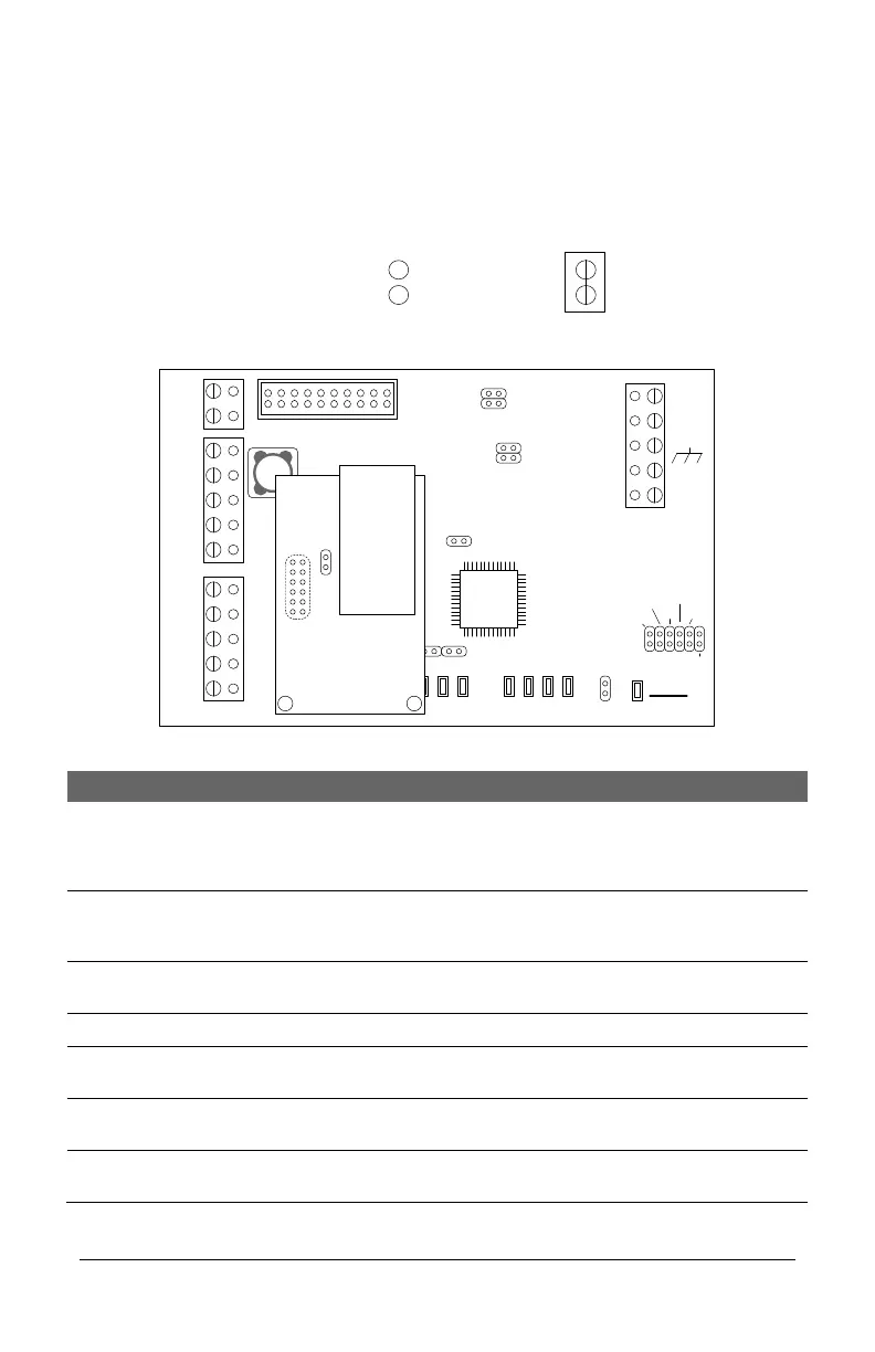
The CIM-LINK modules are jumpered as indicated in the table below depending on its
function.
Figure 6 – CIM-LINK Module Jumpers
TD1
RD1
TD2
RD2
GND
RTS
CTS
GND
RTS
CTS
B3 B2 B1 B0
Diag
J2
RESET
-
CAN2
+
EGND
-
CAN1
+
GND
V +
(+12V)
SCKT1
PC106x
J1
J7
J8
J6
J5
CAN2
CAN1
1 2 1 2 1 2 1 2
Rx - COM COM
CAN
CAN - Tx
J3
J4
J9
J12
Power
Good
COM1
COM2
HDR1
J10
J11
Fault
(Flashing)
RJ45
Terminal
Jack
J1
NETCOMP
CIM-LINK
KI-00485E-10-12
Jumper Off
Off = 0
Jumper On
On = 1
Jumper Legend
CIM-LINK Module Jumper Locations
Short momentarily when the
CIM-LINK has been re-
configured, otherwise leave the
jumper off.
Runs the CIM-LINK in
Diagnostic Mode. See CIM-LINK
Diagnostics section.
Global Master or Group
Master
When connected on a single
ACU communication loop
When connected on a multiple
ACU communication loop
CAN 1 Termination
Jumpers