Keysight CXG, EXG, and MXG X-Series Signal Generators Service Guide 197
RF Assembly
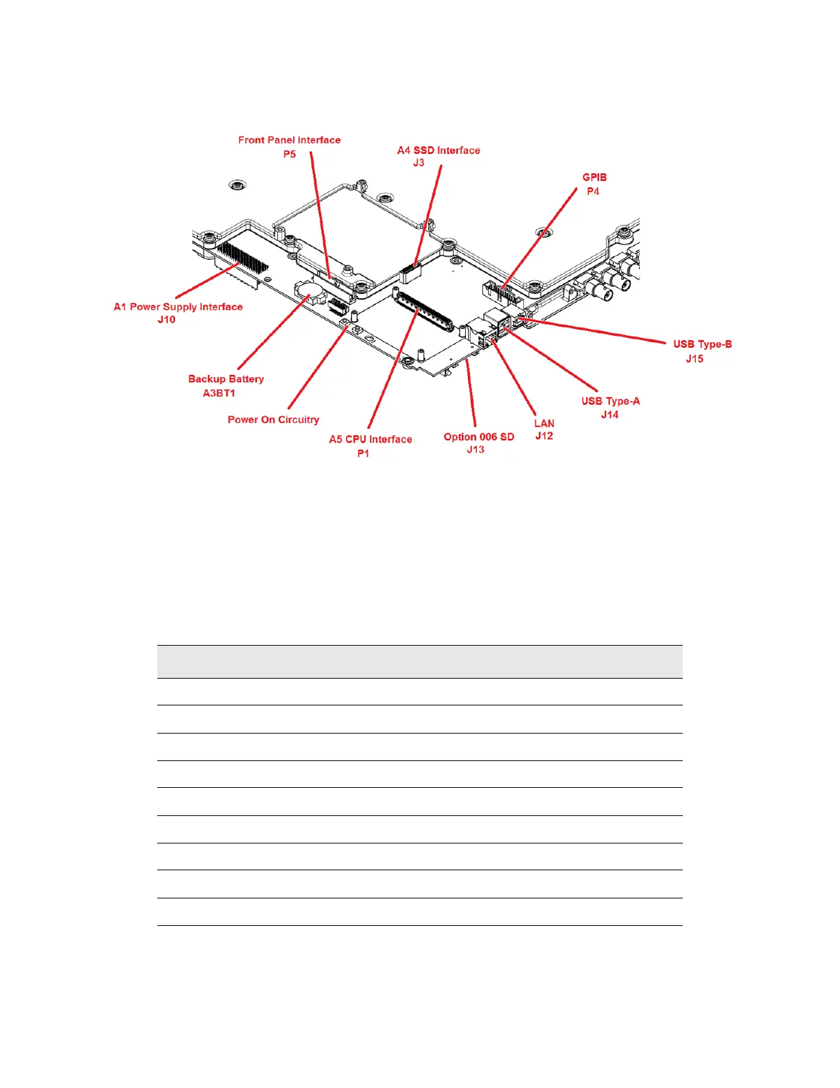
A3 RF Assembly Overview
Figure 10-2 Instrument Interface Locations – A3 RF Assembly
Rear Panel BNC Input / Output Section
There are nine different rear panel BNC inputs and outputs that are used for
triggering the instrument, triggering an external device, providing a low
frequency function generator, locking the references of multiple instruments,
and other functions. A list of these connectors can be seen in Table 10-4, along
with other relevant information for each.
Table 10-4 Rear Panel BNC Input / Output Connectors
Connector Impedance Usage Typical Level Damage Level
EXT 1 50 Ω Input ±1 Vp 5 Vrms or 10 Vp
EXT 2 50 Ω Input ±1 Vp 5 Vrms or 10 Vp
LF OUT 50 Ω Output Settable n/a
SWEEP OUT Low Output 0-10 V Ramp n/a
PULSE 50 Ω Input 0 V = Off, +1 V = On ≤ −0.3 and ≥+5.3 V
TRIG 1 High Input / Output TTL or CMOS ≤ −0.5 and ≥+5.5 V
TRIG 2 High Input / Output TTL or CMOS ≤ −0.5 and ≥+5.5 V
REF IN 50 Ω Input -3.5 to +20 dBm
10 MHz OUT 50 Ω Output > +4 dBm n/a