446 Keysight EXG and MXG X-Series Signal Generators User’s Guide
Using the N5102A Digital Signal Interface Module for N5172B/82B with Option 003/004 and
653/655/656/657
Operating the N5102A Module in Input Mode
2. Select the logic type required for the device being tested.
A caution message is displayed whenever a change is made to the logic types, and a softkey
selection appears asking for confirmation.
3. Refer to Figure 17-18. Press the Port Config softkey.
In this menu, select either a serial, parallel, or parallel interleaved data transmission.
4. Select the port configuration for the device being tested.
Configuring the Clock Signal
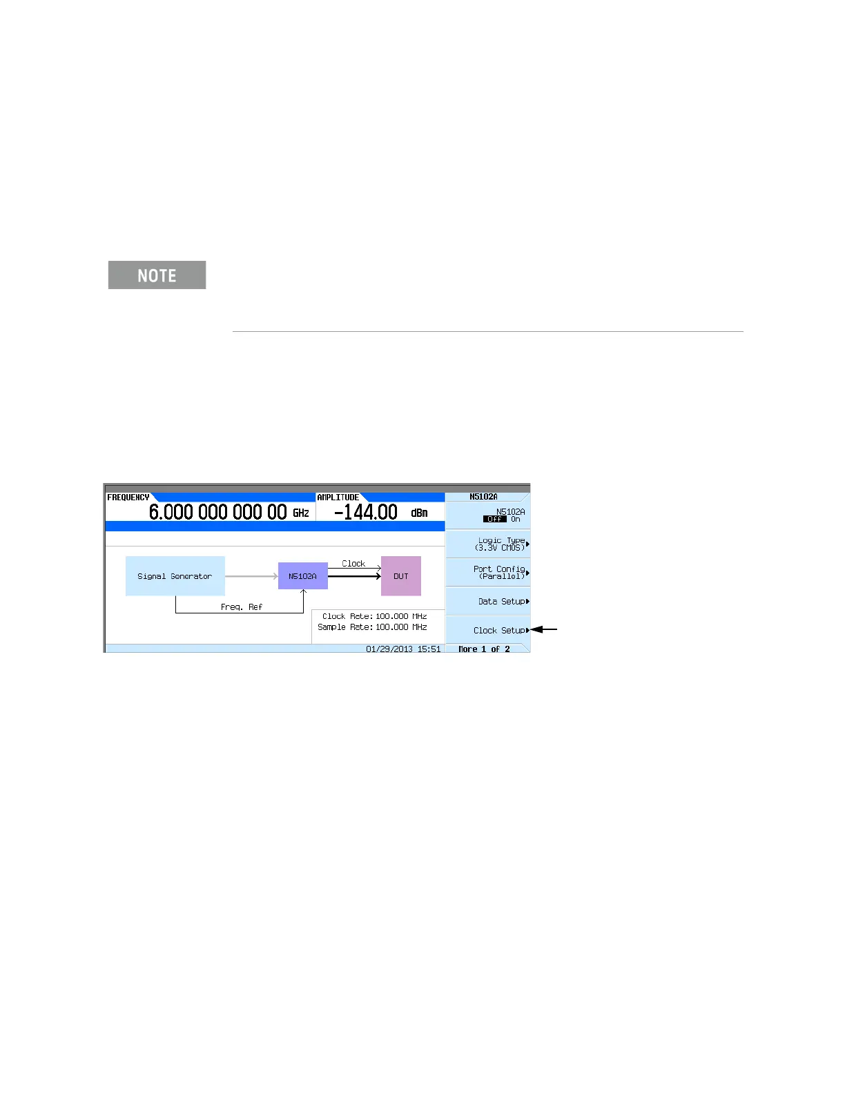
1. Refer to Figure 17-19. Press the Clock Setup softkey.
Figure 17-19 Clock Setup Menu Location
From this softkey menu, set all of the clock parameters that synchronize the data between the
N5102A module and the device. From this menu, the clock signal phase can be changed so the
clock occurs during the valid portion of the data. Figure 17-20 shows the clock setup menu.
If the device or external clock does not match the frequency, one of the following error
messages will appear on the signal generator:
803 Digital module input FIFO overflow error; There are more
samples being produced than can be consumed at the
current clock rate. Verify that the digital module clock
is set up properly.
This error is reported when the digital module clock setup is not
synchronized with the rate the samples are entering the digital
module. Verify that the input clock rate matches the specified
clock rate under the clock setup menu.
Within the data and clock setup softkey menus, some softkeys function relative to the current
configuration. Softkeys that are grayed out are not available for the current setup. Refer to the
help text to determine which parameter is causing the softkey to be unavailable. Press the
Help
key on the signal generator front panel and then the softkey that is unavailable.
Accesses the Clock Setup
Menu
 Loading...