2 Base Matrix Configuration
158 Keysight 34934A User’s Guide
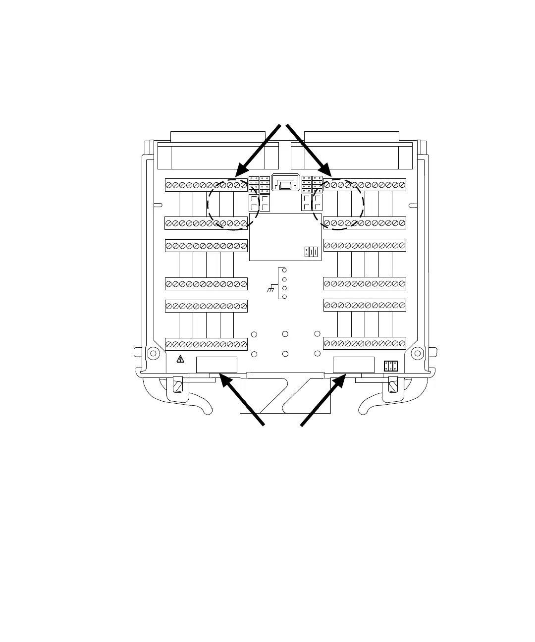
Below is an illustration of the possible locations for making row signal connections
to the 34934T-002:
The following subsection outlines how to make row connections to extension
headers J24 and J25.
Extension Header (Row Signal) Wiring for 8x64
The position of extension
headers J24 and J25 are marked on the 34934T-002’s silk-screen. Oriented with
+/- 100V
J24 J25
CONFIG
JUMPERS
34934T OPT002
1 Wire
OPERATION
8X64
ID
JUMPERS
U
N
U
S
E
D
1 0
R 1 R 2
R 3 R 4
R 5
R 6
R 7
R 8
1
2
34
33
34
35 36
37
38
39 40
5
6
78
1
2
34
33
34
35 36
37
38
39 40
5
6
78
9
10
41
42
47
48
15 16
11 12
43 44
49 50
17 18
13 14
45 46
51 52
19 20
21
22
53
54
59
60
27 28
23 24
55 56
61 62
29 30
25 26
57 58
63 64
31 32
9
10
41
42
47
48
15 16
11 12
43 44
49 50
17 18
13 14
45 46
51 52
19 20
21
22
53
54
59
60
27 28
23 24
55 56
61 62
28 30
25 26
57 58
63 64
31 32
JUMPERSID
1
0
U
N
U
S
E
D
You can connect row signals to the screw terminals here...
...or to the central 16 pins of extension headers J24 and J25 here.