Base Matrix Configuration 2
Keysight 34934A User’s Guide 159
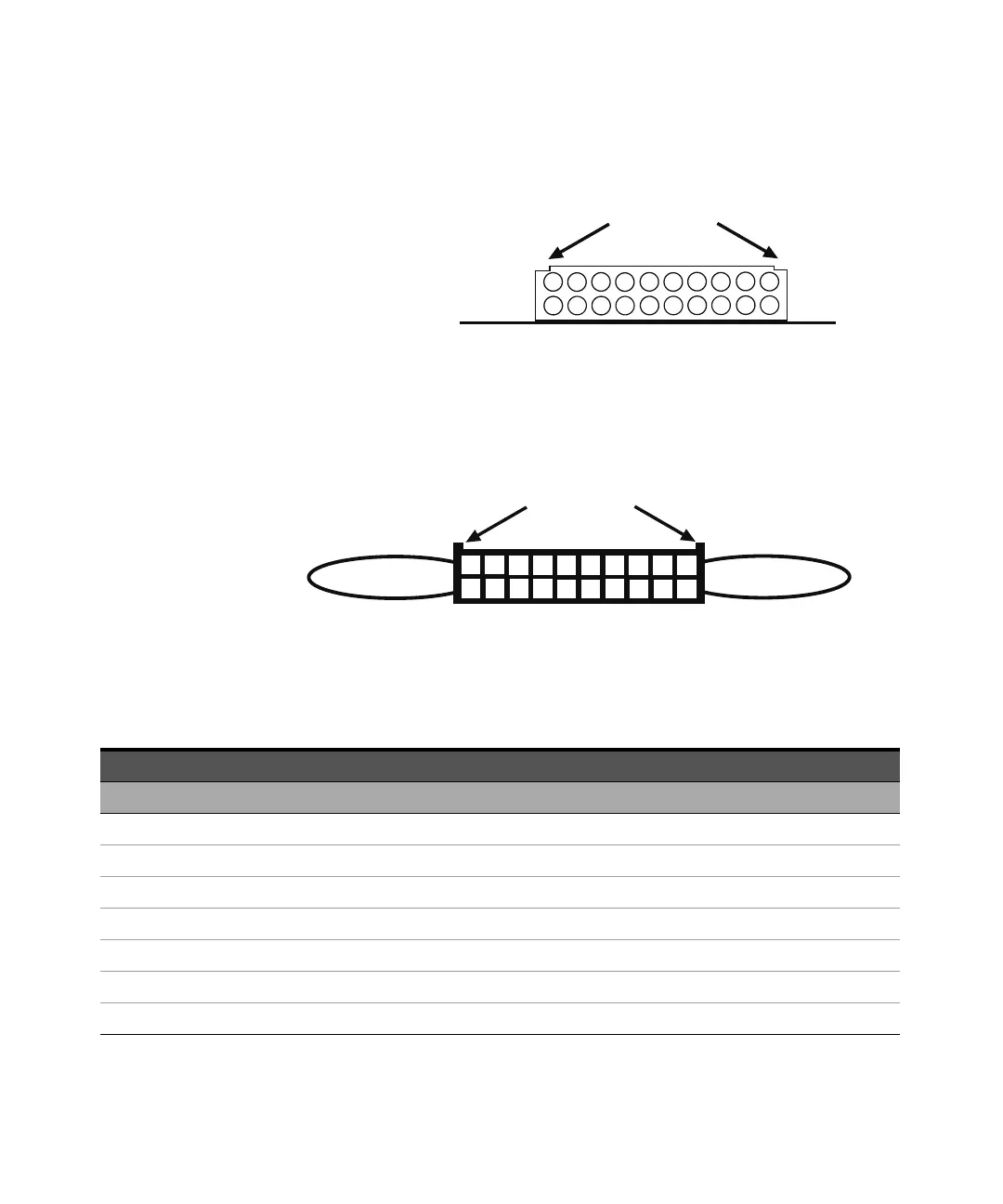
the terminal side of the board up, the pin numbers for these headers are shown
below.
The supplied 20-pin terminators are identical, but the pin assignments for 8x64
are not (rows 1-4 are on J24; rows 5-8 are on J25). The terminal
numbers—corresponding to the headers—are shown below. Pay careful attention
to the indexing keys on the connectors, to correctly identify terminal #1.
You must fabricate custom cabling to make row signal connections to the central
16 pins (3-18) of these headers, using the pin assignments below. The supplied
blue terminators accommodate 22 AWG coated wire, fitted to “crimp-to-wire”
contacts with latch tabs (FCI part #76357-301LF or equivalent).
34934T-002: Extension Header Pin Assignments for 8x64
182
10
4
6
8
12
14
16
20
1
3
5
7
9
11
13
15
19
17
Extension Headers J24 and J25
Polarization Notches
circuit board
18
12
14
16
20
2
1
4
3
6
5
8
7
10
9
11
13
15
19
17
Safety Interlock
Continuity Jumper
connects
pins 19 and 20
Indexing keys
Jumper for pins
1 and 2
20-Pin Terminators for J24 and J25
—
Headers J24 Headers J25
Description Pin Description Pin Description Pin Description Pin
No connect 1 No connect 2 No connect 1 No connect 2
R1 3 R1 4 R5 3 R5 4
No connect 5 No connect 6 No connect 5 No connect 6
R2 7 R2 8 R6 7 R6 8
No connect 9 No connect 10 No connect 9 No connect 10
R3 11 R3 12 R7 11 R7 12
No connect 13 No connect 14 No connect 13 No connect 14