2 Base Matrix Configuration
168 Keysight 34934A User’s Guide
– The extension headers on the opposite (unused) side of the 34934C-002 do
not require a safety interlock terminator; these will be hidden by the
configuration block’s cover.
34934C-002 Configuration Block: Wiring
The next two subsections outline options for making row and column wiring
connections to the configuration block.
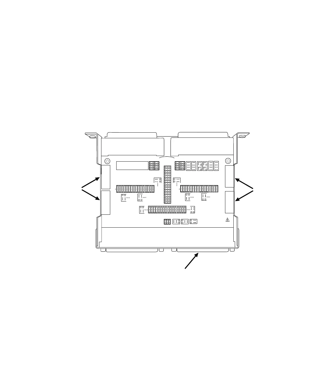
Extension Header (Row Signal) Wiring to the 34934C-002
Below is an illustration of the possible locations for making row signal connections
to the 34934T-002.
Typically, you could make both row and column connections to each module by
fabricating custom cabling terminating in female D-Sub connectors. These attach
to the configuration block’s male D-Sub connectors P1 and P2. For 8x64, all rows
connect to P2.
J15
J16
8 X _ _
16 X 32
8 X _ _
16 X 32
JUMPERS
8X32 8X64
16X32
(P2)
ENABLE ROW ACCESS
J
6
J
5
EXTEND ROWS LEFT (J5), (J6)
EXTEND ROWS RIGHT (J3), (J4)
CONFIG
CONFIG
JUMPERS
JUMPERS
8X32 8X64
16X32
+
-
100V
J
4
J
3
34934C OPT002
1W/2W/MIXED
J11J13 J12
J10
SET J10 = J11 = J12 = J13
SET J10 = J11 = J12 = J13
J7
J7
J7
ID
J8
(P2)
DISABLE ROW ACCESS
Female D-Sub connector (to 34934A)
Female D-Sub connector (to 34934A)
Male D-Sub connector P1 (to field wiring)
Male D-Sub connector P2 (to field wiring)
You could
connect
rows to
extension
headers
J5 and J6
Typically, you would
connect rows to
D-Sub connector P2
You could
connect
rows to
extension
headers
J3 and J4