Base Matrix Configuration 2
Keysight 34934A User’s Guide 169
Alternately, you may choose to connect only columns (typically test points on
your DUT) to the D-Subs. There may be physical or electrical advantages in
making your row connections (typically measurement devices) to the
configuration block’s blue extension connectors J3, J4, J5 and J6. To provide this
flexibility, two extension headers are provided on each side of the configuration
block.
You must have set the jumpers (in “Placing Row Extension Jumpers on the
34934C-002 Configuration Block” on page 164) to extend rows to two of the four
headers. We’ll call these the “live” headers.
In “Placing Safety Interlock Continuity Jumpers on the 34934C-002 Configuration
Block” on page 167, you will have installed the supplied blue terminators in the
live headers on the configuration block.
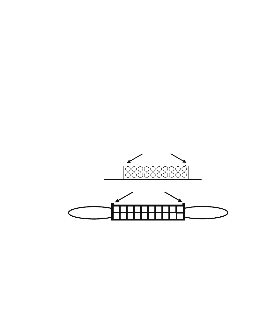
You can now make row connections to these headers, by utilizing the central 16
pins (3-18) on the snap-in terminators. The extension header’s supplied
terminator is shown below. Pay careful attention to the polarizing notches for
identification of pin 1:
You must fabricate custom cabling to make row signal connections to the central
16 pins (3-18) of these headers, using the pin assignments below. The supplied
blue terminators accommodate 22 AWG coated wire, fitted to “crimp-to-wire”
contacts with latch tabs (FCI part #76357-301LF or equivalent).
182
10
4
6
8
12
14
16
20
1
3
5
7
9
11
13
15
19
17
18
12
14
16
20
2
1
4
3
6
5
8
7
10
9
11
13
15
19
17
Extension Headers J3, J4, J5 and J6
Polarizing Notches
circuit board
Supplied Jumper
from Pin 1-2;
Polarizing Notches
Supplied Extension Terminators
Safety Interlock
Terminator for
Pins 19 & 20