2 Base Matrix Configuration
184 Keysight 34934A User’s Guide
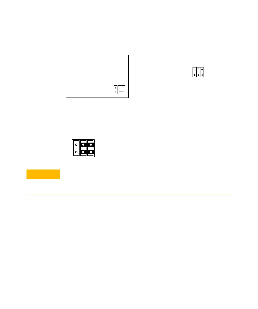
guidance is provided (on the 16x32 removable overlay) as shown below left; the ID
jumper block is shown at right with jumpers removed.
To set the correct ID code for 16x32, place two horizontally positioned jumpers as
shown below.
Placing Safety Interlock Continuity Jumpers for 16x32
At the bottom (end
opposite the D-Sub connectors) of the terminal block are two 20-pin extension
headers—marked J24 and J25 on the circuit board. These headers provide access
to the module’s rows. Pins 19 and 20 on each header must be shorted to provide
continuity for the module’s safety interlock function.
Location of
placement
guidance
for ID
Jumpers
ID JUMPER block
34934T OPT002
1Wire
OPERATION:
16X32
ID
JUMPERS
U
N
U
S
E
D
1 0
The ID jumpers MUST correspond to the matrix configuration set by the
CONFIG jumpers in the previous step. The instrument firmware functions
based on the ID it detects from the (ID) jumper positions and assumes the
CONFIG jumpers are set accordingly.