Base Matrix Configuration 2
Keysight 34934A User’s Guide 83
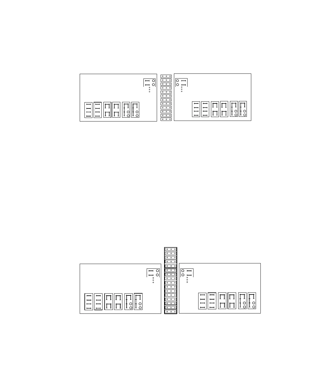
This optional step is implied by the silk-screened guidance provided on the board
at either side of jumper block J7, illustrated below.
Placing Row Extension Jumpers on the 34934C-001 Configuration Block
The jumpers in 16x3 jumper block J7 (at board center) determine if row
connections can be made from the left or right side of the board (i.e. they “extend”
the row signal connection points out to only one of the two pairs of blue 20-pin
connectors at the sides of the configuration block).
Note that “row connections” at minimum include the connections between
modules in the matrix, but may also include your access from field wiring to the
matrix rows.
Setting these jumpers provides you the flexibility to plan how to route your custom
cabling, depending on slot placement of the individual 34934A modules and their
corresponding 34934C-001 blocks.
The following illustration shows the jumper block J7, along with the relevant
guidance provided on the board’s silk-screen for jumper placement:
EXTEND ROWS LEFT (J5)
EXTEND ROWS RIGHT (J4)
ALSO EXTEND TO (J6), (P2)
4X32 4X64
4X128
USE
JUMPERS
CONFIG
USE
JUMPERS
CONFIG
4X32 4X64
4X128
J7
J7
ALSO EXTEND TO (J3), (P2)
EXTEND ROWS LEFT (J5)
EXTEND ROWS RIGHT (J4)
ALSO EXTEND TO (J6), (P2)
4X32 4X64
4X128
USE
JUMPERS
CONFIG
USE
JUMPERS
CONFIG
4X32 4X64
4X128
J7
J7
J7
ALSO EXTEND TO (J3), (P2)