Base Matrix Configuration 2
Keysight 34934A User’s Guide 85
If you plan to connect row signals to the D-sub connectors, place two 2x8
jumpers as shown below.
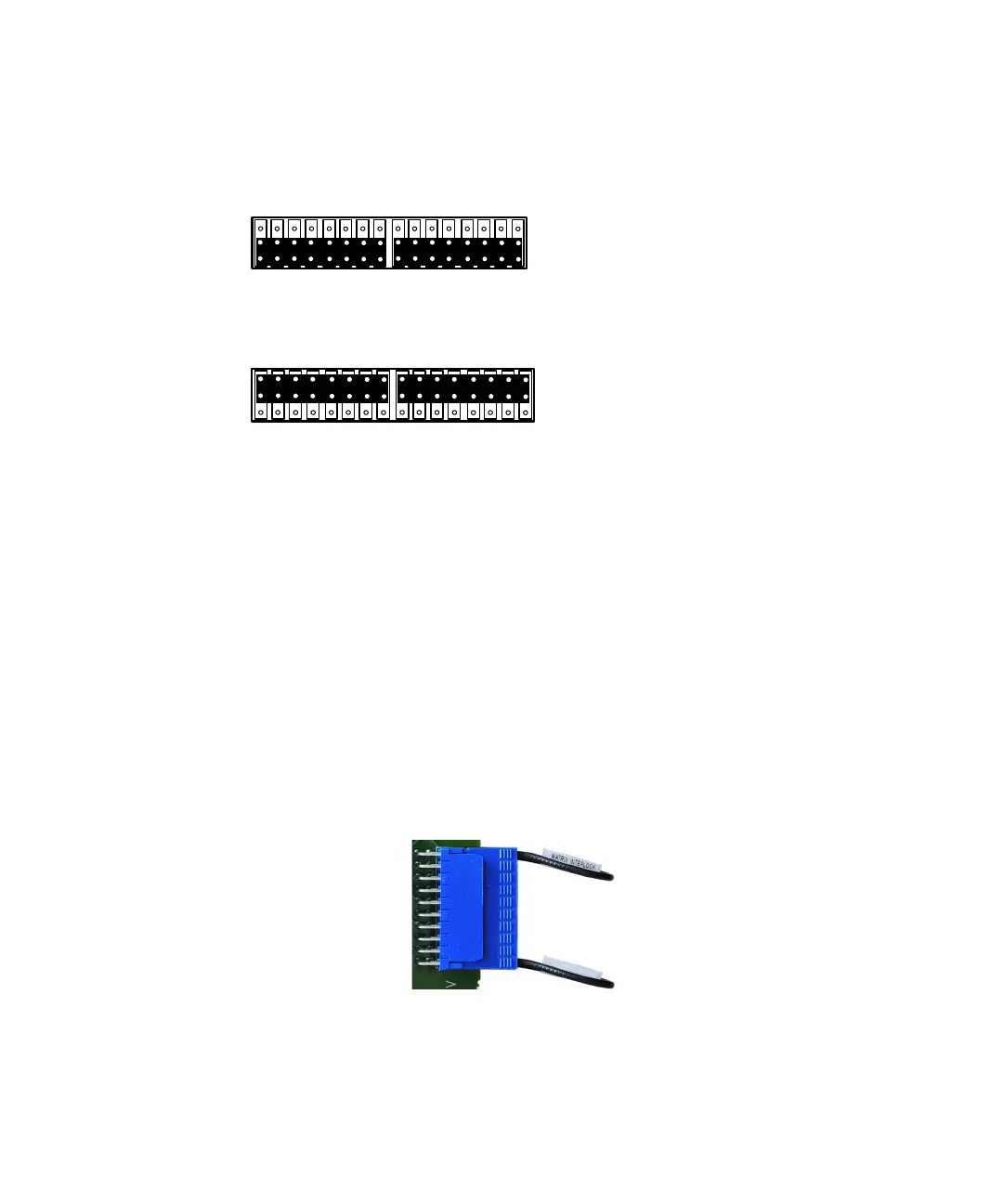
If you do not need to connect row signals to the D-sub connectors, place two
2x8 jumpers as shown below.
Note that by not routing signals to the D-sub connectors, module bandwidth may
be preserved and capacitive loading minimized.
Placing Safety Interlock Continuity Jumpers on the 34934C-001
Configuration Block
At each side of the configuration block are a pair of 20-pin
extension headers. On the right side are labeled J3 and J4; on the left side are J5
and J6. In all cases, pins 19 and 20 are the safety interlock pins.
These headers provide for row extension and row signal access, depending on the
placement of the jumpers in J7. You must have set the jumpers to extend rows
either to the left or right side (of the configuration block) (see “Placing Row
Extension Jumpers on the 34934C-001 Configuration Block” on page 83).
To provide continuity for the module’s safety interlock function, pins 19 and 20 on
both extension headers on the selected side (left or right) must be shorted.
– For each of these headers, install one of the supplied keyed 20-pin terminators
securely in that header, as shown below.
The supplied terminators incorporate both the shorting jumper for pins 19 and
20 and a jumper precluding connection to pins 1 and 2.