2 Calibration Procedures
62 Keysight DAQ970A/DAQ973A Service Guide
7 A “Calibration Step Succeeded” message indicates success; if the display
shows “Calibration Step Failed”, check the input value, range, function, and
entered calibration value, and repeat the calibration step.
8 Repeat step 5 to step 7 for each gain calibration point.
9 Store the new gain calibration constants (see “Storing calibration constants”
on page 46).
DC current gain calibration
1 Ensure that you have read the “Test Considerations” on page 47 and the “Gain
and flatness adjustment considerations” on page 55.
2 Ensure that you follow the sequence listed in the “Calibration Adjustment
Sequence” on page 51.
3 This procedure will measure and adjust the input signal from the calibrator
source connected to Channel 321 (DC current). See the connections in “Input
test signal” on page 38.
4 Select Channel 321 and configure the function in the order shown in the table
below and enable Channel Monitor on the selected channel before each test
(see “Channel monitor” on page 50).
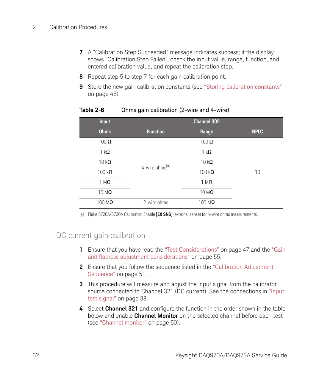
Table 2-6 Ohms gain calibration (2-wire and 4-wire)
Input Channel 302
Ohms Function Range NPLC
100 Ω
4-wire ohms
[a]
[a] Fluke 5720A/5730A Calibrator: Enable [EX SNS] (external sense) for 4-wire ohms measurements.
100 Ω
10
1 kΩ 1 kΩ
10 kΩ 10 kΩ
100 kΩ 100 kΩ
1 MΩ 1 MΩ
10 MΩ 10 MΩ
100 MΩ 2-wire ohms 100 MΩ