36 Keysight M8000 Series of BER Test Solutions Installation Guide
2 Installing Modules
2 Locate the module insertion/extraction handles at both ends of the
instrument module. Extend the ends of both handles by pulling them
inwards towards each other. Then fully open the handles by pivoting
them out towards you.
3 Align the module’s PCA board with the guide rails on both ends of the
M9505A AXIe chassis. If the module has metal plates covering the
board, be sure to insert the PCA board and not the metal plates into
the rails.
4 Push the module into the chassis slot until the leading edges of the
insertion/extraction latches rest against the front surface of the
chassis. The insertion/extraction latch handles should be
perpendicular to the front surface of the chassis (aligned with the
direction of module insertion). Nudge the module gently inward to
allow the latches to engage.
5 Using your thumbs, press inward firmly on the insertion/extraction
handles until the module is seated firmly in the chassis backplane. The
module front panel should lie flush with the chassis front panel.
6 Push the handle ends towards the edge of the chassis to tuck them
away.
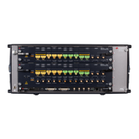
7 Tighten the retaining screws on either end of the module to ensure the
ground connection.
Figure 19 Tighten retaining screws
8 Locate the synchronization cable that was shipped with the M8051A
module as shown in
Figure 20 on page -36.
Figure 20 Standard synchronization cable M8041-61601
 Loading...

