18 M8100 Series Arbitrary Waveform Generators Getting Started Guide
1 Introduction
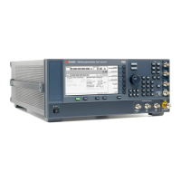
M8008A Front Panel Connectors
Table 5 M8008A Front Panel Connectors
The inputs of the M8008A module are sensitive to static electricity.
Therefore, take necessary anti-static precautions, such as wearing a
grounded wrist strap, to minimize the possibility of electrostatic damage.
Connector Description
Sync In Reserved for future use
Sync Out A, B, C, D This output is used to synchronize two or more M8199A / M8199B modules to a
common system clock. It is also required for the M8198A module. It is connected to the
Sync In of the M8198A / M8199A / M8199B module.
Sample Clk Out 1 and
Sample Clk Out 2
Sample clock outputs, connected to “Sample Clk In” on up to four M8199A modules.
Each pair of sample clock outputs can be turned on and off independently.
Sample clock outputs, connected to “Sample Clk In” on the M8198A module.
Refer to Table 8 for cabling instructions.
Sys Trig In A/B Reserved for future use.
Ref Clk In This input allows locking the clock frequency to an external 10 or 100 MHz reference
clock.
Ref Clk Out The reference clock output is used to provide a 10 MHz or 100 MHz reference clock to
the DUT or other test equipment.
Ref Clk Out 16G The reference clock output is used to provide an 8 GHz … 16 GHz reference clock to the
DUT or other test equipment. It can be used as a precision time-based reference signal
for DCA sampling oscilloscopes.