32 M8100 Series Arbitrary Waveform Generators Getting Started Guide
1 Introduction
M8199B Module Components
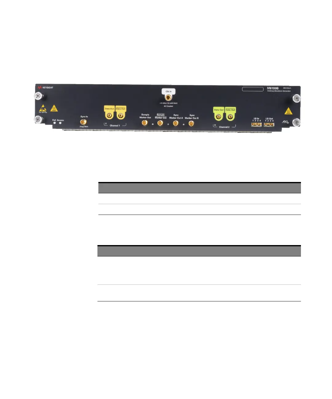
Figure 11 displays the front panel of the M8199B module:
Figure 11 M8199B module front panel
As displayed in the image above, the M8199B module has the following
components.
Table 14 Front Panel LEDs
Table 15 Insertion/Extraction and Retaining
Front Panel LED Active when... Color
Fail power-up fault condition red
Access power-up ready state green
Component Description
Retaining screws The screws on both ends of the module are used to retain the module tightly
inside the M9505A AXIe Chassis slot once you have fully placed it inside the
chassis. To remove the module, you first need to loosen these screws ensuring
that these screws disengage completely.
Module Insertion/Extraction
Handles
The handles on both sides of the module to insert or eject the module from the
slot of the M9505A AXIe Chassis.