Do you have a question about the Keysight M8190A and is the answer not in the manual?
Details warranty limitations and disclaims implied warranties for product.
Warns about ESD sensitivity of front-panel connectors and recommends safe environment.
States disclaimer of warranties and limitation of liability for the manual.
Describes terms for hardware/software use under license agreements.
Explains rights for U.S. Government use of software and technical data.
Explains CAUTION and WARNING notices for hazard awareness and user safety.
Lists general precautions for safe operation and compliance with chassis safety.
Guides on inspecting shipping container and instrument for damage or defects.
Notes the product is Safety Class 3 and may be impaired if used improperly.
Specifies operating temperature, humidity, and altitude limits for the instrument.
Reminds to verify all safety precautions are taken before applying power.
States the M8190A requires an AXIe mainframe for operation.
Prohibits operation in environments with flammable gases or fumes.
Advises against user removal of covers; service by qualified personnel only.
Explains the general recycling mark symbol.
Lists previous editions of the user guide and associated firmware versions.
Details the available modular options for the M8190A and their comments.
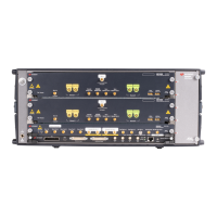
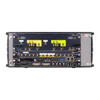
Describes the inputs and outputs and status LEDs on the front panel.
Highlights differences in front panel inputs/outputs for the one-channel model.
Introduces the block diagram and operational modes of the instrument.
Explains the procedure for installing software licenses for instrument options.
Introduces the chapter covering the M8190A Soft Front Panel.
Describes three methods for launching the M8190A Soft Front Panel application.
Provides an overview of the GUI elements including title, status, and menu bars.
Explains the window to inspect IVI driver calls and SCPI commands used.
Describes the window used to view errors, warnings, and information messages.
Details configuring sample and reference clocks, including internal/external selection.
Explains how to configure the outputs (Channel 1 and Channel 2) of the module.
Covers configuration of external trigger/event inputs and marker outputs.
Allows creation of standard waveform types like sine, square, and triangle.
Used to create signals composed of multiple tones, equally or arbitrarily spaced.
Enables creation of baseband and IF/RF digitally modulated signals.
Provides controls for importing, scaling, and resampling waveform files.
Allows creation, configuration, and sending of sequence configurations.
Displays status and controls for starting/stopping signal generation.
Defines the format for ASCII files used for compensating signal responses.
Explains how the Soft Front Panel connects to the M8190 Firmware.
Introduces the chapter describing sequencing capabilities with Option -SEQ.
Explains that sequencing capabilities are limited without the Option -SEQ.
Describes the sequencer implementation in a table with sequence vectors.
Defines sequencer granularity as samples played per sync clock cycle.
Explains the hierarchy of segments, sequences, and scenarios.
Defines how segments, sequences, and scenarios begin playing waveform data.
Allows selecting the output signal before starting the sequencer.
Specifies how elements advance to the next or repeat.
Used to influence the sequencer and control waveform generation.
Overviews different trigger modes and their interaction with conditional inputs.
Describes various sequence modes and their behavior based on trigger and arm modes.
Describes dynamically selecting segments/sequences to be played via software or external input.
Allows setting pauses between segments with adjustable granularity.
Details limitations related to segment length and linear playtime.
Introduces digital up-conversion capabilities with Option -DUC.
Explains the instrument's ability to provide IQ modulated signals at its output.
Describes functionality requiring Option -SEQ for changing settings at run-time.
Explains how to scale the amplitude of the DAC output signal.
Mentions coarse delay availability but inability to change at run-time in up-conversion modes.
States doublet mode is available for digital up-conversion modes with frequency band mirroring.
Introduces streaming capabilities for generating waveforms with infinite playtime.
Describes switching segments/sequences using dynamic modes for continuous or triggered execution.
Details the ring buffer mechanism for automatic sequence restarts and sample data changes.
Explains updating waveform segments during active generation and switching glitch-free.
Introduces output signals with defined timing for sample streams, called markers.
Explains sample markers used to mark individual samples and their granularity.
Describes the second marker per channel, set in sync clock granularity.
Introduces low phase noise operation with Option -LPN for 2-channel configuration.
Shows a block diagram of the low phase noise configuration.
Explains enabling low phase noise mode via the clock panel checkbox.
Introduces programming M8190A using IVI-COM driver and SCPI commands.
Recommends using IVI drivers for programming and explains connection to firmware.
Details SCPI programming via LAN, supporting VXI-11, HiSLIP, and Socket protocols.
Provides recommendations for programming, including default settings and speed.
Lists SCPI commands related to system status, errors, and help information.
Lists common SCPI commands like *IDN?, *CLS, *ESE, *ESR?, *OPC.
Describes the SCPI status system structure with register groups.
Details commands for arming and triggering sequences and waveforms.
Explains commands related to trigger input sources and events.
Controls binary data transfer byte order (normal or swapped).
Manages instrument-level settings like coupling and multi-module configuration.
Provides commands for managing files and directories on the instrument's memory.
Controls output settings such as normal output state, complement output, and clock source.
Details commands for setting and querying sample frequencies, including low phase noise.
Manages reference clock sources and frequencies for synchronization.
Sets voltages and formats for different output paths (DAC, DC, AC).
Configures output amplitude, offset, high, and low levels for selected paths.
Controls amplitude and offset settings for sample and sync markers.
Sets or queries the type of waveform generation: arbitrary, sequence, or scenario.
Manages sequences made of arbitrary waveforms, linked and looped in user-programmable order.
Directly manipulates the sequencer table, supporting scenarios and idle commands.
Controls arbitrary waveforms and their parameters, including segment creation and data download.
Provides commands for accessing power-on self-tests results.
Manages carrier frequency settings for interpolated modes.
Defines frequency tables usable as carrier frequencies for I/Q data segments.
Defines amplitude scale values for scaling I/Q data segments.
Allows definition of actions (commands) that can be referenced from sequence table entries.
Directory for example custom modulation files for SFP Complex Modulation.
MATLAB example applications demonstrating waveform generation capabilities.
Contains WLAN example waveform file and corresponding M8190A instrument setting.
Lists various VISA examples for C++, COM, and VB programming.
Contains example waveform data files in various formats like TXT, BIN, IQBIN.
Provides information on where to find the performance specifications.
Lists general specifications like power consumption, operating temperature, and humidity.
Specifies minimum clearance requirements for rear and side of the AXIe chassis.
Explains resampling requirements for generating new waveforms with different sampling rates.
Details constraints for resampling, including record length and granularity.
Describes the resampling approach using direct output sample calculation and filtering.
Explains different modes (Timing, Keep-Sample-Rate, Truncate, Repeat) that modify resampling.
| Category | Arbitrary Waveform Generator |
|---|---|
| Model | M8190A |
| Sample Rate | Up to 12 GSa/s |
| Number of Channels | 1 or 2 |
| Interface | PCIe |
| Vertical Resolution | 14 bits |
| Bandwidth | Up to 8 GHz |
| Modulation Formats | FSK, PSK, QAM |
| Resolution | 14 bits |
| Form Factor | AXIe |
| Memory Depth | 2 GSa per channel |
