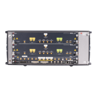
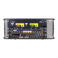
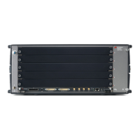
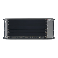
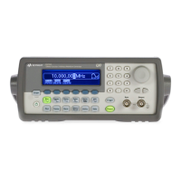
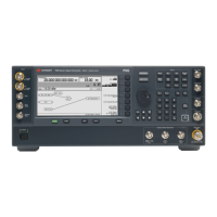
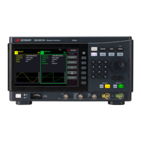
The inputs and outputs of the instrument are available at the front panel:
The analog output signal of channel 1 and channel 2 (DIRECT OUT 1 & DIRECT
OUT 2) are differential outputs of the two Digital to Analog Converters (DAC).
The Outputs can be switched ON or OFF with internal relays.
The analog output signals of channel 1 and channel 2 (AMP OUT 1 & AMP OUT
2) are amplified output signals of the Digital to Analog Converters (DAC). The
Outputs can be switched ON or OFF with internal relays. Two different amplifiers
can be selected. One amplifier is optimized in performance for time domain
applications (DC amplifier) and has differential outputs. The second amplifier is
optimized for RF applications, maximum bandwidth and high output level (AC
amplifier) and has a single-ended output. These two amplifiers are available, if
option -AMP is installed. Option -AMP is SW upgradeable.
The Sample Marker Output (SAMPLE MRK OUT 1 & SAMPLE MRK OUT 2) can be
used to mark the beginning of a certain segment or a certain position in the
analog signal to e.g. trigger an external device. It has a timing resolution of one
sample clock period.
The Synchronization Marker Output (SYNC MRK OUT 1 & SYNC MRK OUT 2) has
a similar functionality as the Sample Marker Output. It has a timing resolution of
64 sample clock periods in 12 bit mode (48 sample clock periods in 14 bit mode
and 24 IQ sample pairs in interpolated modes when using Option -DUC).
 Loading...
